
Lifting appliance

A lifting device and lifting iron technology, which is applied in the direction of transportation and packaging, load hanging components, etc., can solve the problems that the hole-shaft type body lifting structure cannot be used, the space of the fuel tank cover is tight, and the lifting device is large in volume, etc., and the structure is achieved. Compact, scientific and reasonable design, strong versatility

Inactive Publication Date: 2008-09-24
XD JINAN TRANSFORMER
View PDF0 Cites 3 Cited by
  • Summary
  • Abstract
  • Description
  • Claims
  • Application Information

AI Technical Summary

Problems solved by technology

[0002] The existing lifting device is bulky and cannot lift some objects with a small clamping space. For example, the width of the upper yoke of the iron core of a super-capacity transformer with a five-column core structure is correspondingly smaller than that of the core column, which causes clamping The web is narrowed, and the space between the upper clamp—iron core—fuel tank cover is tight, and the traditional hole-shaft body lifting structure cannot be adopted.

Method used


Image

  • Lifting appliance

Examples


Embodiment Construction

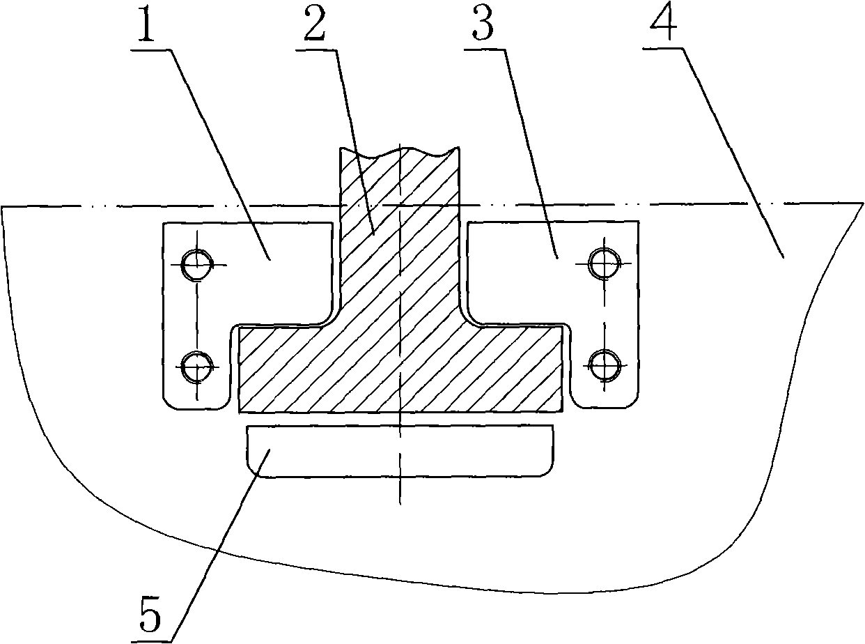
[0010] A hoisting device, including a web fixing part, a T-shaped hanging iron 2 and a cover plate, such as figure 1 There are three web fasteners shown, two L-shaped web fasteners 1, 3 and a one-shaped web fastener 5, two L-shaped web fasteners 1, 3 and one-shaped web fasteners The pieces 5 are welded to the web 4 of the object to be hung at intervals and enclose an inverted T-shaped area. The T-shaped hanging iron 2 is inverted in the inverted T-shaped area, and the upper end of the inverted T-shaped hanging iron 2 is extended out of the T-shaped area. The cover plate is fixed on the web fixing parts 1 and 3 by bolts. The T-shaped hanging iron 2 is located in the inverted T-shaped space formed by the cover plate and the web fixing member, and will not fall off, and the T-shaped hanging iron 2 can be lifted by lifting equipment to lift the object to be lifted.


PUM


Abstract

The invention discloses a lifting device which comprises a ventral shield fastening part, a T-shaped hanger and a cover plate, the ventral shield fastening part is fixed on the ventral shield of an object to be lifted, the T-shaped hanger and the cover plate can be detachably connected and fixed with the ventral shield fastening part, the T-shaped hanger is inverted in an inverted T-shaped space formed by the cover plate and the ventral shield fastening part, and the upper end of the inverted T-shaped hanger exposes. The lifting device has the advantages of compact structure, small occupied space, good intensity, scientific and reasonable design as well as good manufacturability and commonality. The lifting device is especially suitable for the lifting of a high capacity transformer body with a five-column type iron core structure.

Description

(1) Technical field [0001] The invention relates to a hoisting device, in particular to a hoisting device with a small clamping space for objects to be hoisted. (2) Background technology [0002] The existing lifting device is bulky, and cannot be lifted for some objects with small clamping space. For example, the width of the upper yoke of the iron core of the super-large capacity transformer using the five-column core structure is correspondingly smaller than the size of the core column, which results in a clamping piece. The web is narrowed, and the space between the upper clamp - the iron core - the fuel tank cover is tight, and the traditional hole-shaft type lifting structure cannot be used. (3) Contents of the invention [0003] The technical problem to be solved by the present invention is to provide a hoisting device that occupies a small space. [0004] In order to solve the above technical problems, the present invention includes a web fixing member, a T-shaped...

Claims


Application Information

Patent Timeline
Patent Type & Authority Applications(China)
IPC IPC(8): B66C1/22
Inventor 杨籍中李宏文张同元卢忠民宋甲武
Owner XD JINAN TRANSFORMER
Learn More