
Lifting mechanism for shaft products

A product and shaft technology, applied in the field of lifting mechanism, can solve problems such as low production efficiency, and achieve the effect of improving productivity and simple structure

Inactive Publication Date: 2022-07-12
台州普宇智能科技有限公司
View PDF0 Cites 0 Cited by
  • Summary
  • Abstract
  • Description
  • Claims
  • Application Information

AI Technical Summary

Problems solved by technology

At present, when shaft products are processed in multiple processes, manual transfer is mostly used to transfer the shaft to the next process, and its production efficiency is low

Method used


Image

  • Lifting mechanism for shaft products
  • Lifting mechanism for shaft products
  • Lifting mechanism for shaft products

Examples


Embodiment Construction

[0014] The following descriptions are only preferred embodiments of the present invention, which do not limit the protection scope of the present invention. The present invention will be further described below with reference to the accompanying drawings and embodiments.

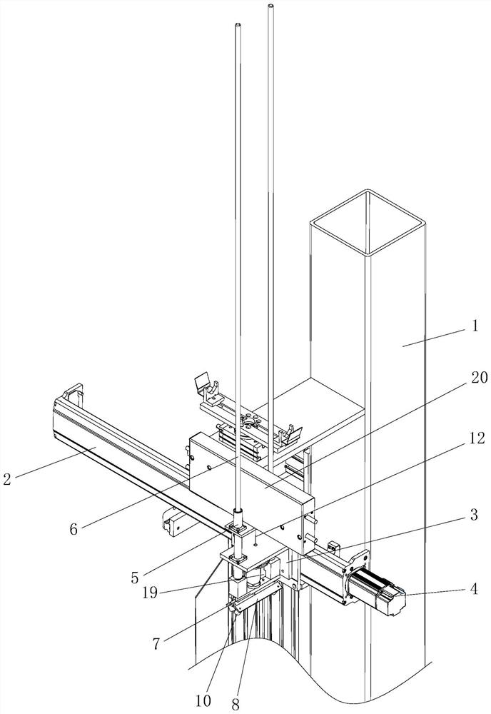
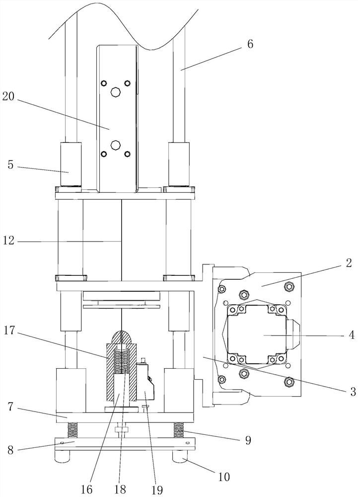
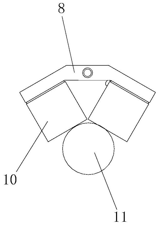
[0015] example, see Figure 1 to Figure 4 Shown: a lifting mechanism for shaft products, including a bracket 1, a horizontal slide rail 2 is connected to the bracket 1, and an automatic slider 3 is arranged on the horizontal slide rail 2, wherein the horizontal slide rail 2 Both ends of the rail 2 are connected with a screw rod, the inner end of the automatic sliding block 3 is provided with a screw hole that is adapted to connect with the screw rod, and one end of the horizontal slide rail 2 is installed with a deceleration motor 4, and the output of the deceleration motor 4 The shaft and the lead screw are connected through a coupling, and the forward or reverse automatic sliding of the automatic slider 3 ...


PUM


Abstract

The invention discloses a lifting mechanism for shaft products, which comprises a support and is characterized in that the support is connected with a horizontal sliding rail, and the horizontal sliding rail is provided with an automatic sliding block; a sliding sleeve is arranged at the outer end of the automatic sliding block, a guide rod is installed in the sliding sleeve, a lifting plate is connected to the lower end of the guide rod, a grabbing plate is connected to the lower side of the lifting plate, and a magnet assembly is connected to the lower side of the grabbing plate. A lifting device is arranged on the upper side of the lifting plate and connected with the lifting plate through a rope. The lifting device comprises two air cylinders which are opposite in the axial direction, piston rods of the two air cylinders are connected with installation bases respectively, pulley blocks formed by a plurality of pulleys are installed on the installation bases, and the rope is wound between the two pulley blocks. The lifting device is simple in structure and beneficial to improving production efficiency, the lifting device adopts a combined structure of the air cylinder, the pulley block and the rope, the acting force of the air cylinder is constant, the constant output force of the air cylinder can be controlled through the air valve, and the lifting device is suitable for lifting various shafts with different weights.

Description

technical field [0001] The invention belongs to the technical field of mechanical equipment, and in particular relates to a lifting mechanism for shaft products. Background technique [0002] The production of various shaft products requires multiple processes. At present, when shaft products are processed in multiple processes, most of them are manually transferred to transfer the shaft to the next process, which has low production efficiency. SUMMARY OF THE INVENTION [0003] The purpose of the present invention is to provide a lifting mechanism for shaft products in view of the above-mentioned deficiencies in the prior art. [0004] The technical scheme adopted in the present invention is: a lifting mechanism for shaft products, comprising a bracket, a horizontal sliding rail is connected to the bracket, and an automatic sliding block is arranged on the horizontal sliding rail; the automatic sliding block The outer end is provided with a vertical axial sliding sleeve,...

Claims


Application Information

Patent Timeline
IPC IPC(8): B23Q7/00B23Q7/14B66F7/04B66F7/28
CPCB23Q7/005B23Q7/008B23Q7/14B66F7/04B66F7/28
Inventor 张学斌
Owner 台州普宇智能科技有限公司
Learn More