
Vacuum heat collecting tube

A technology of vacuum heat collecting tubes and vacuum layers, which is applied in solar heat collectors, solar heat collectors using working fluids, heating devices, etc., can solve problems such as increasing the number of joints, increasing the difficulty of operation, and increasing the difficulty of maintaining vacuum. Achieve the effects of reducing costs, improving absorption efficiency, and reducing manufacturing precision requirements

Inactive Publication Date: 2008-09-24
SOUTHEAST UNIV
View PDF1 Cites 14 Cited by
  • Summary
  • Abstract
  • Description
  • Claims
  • Application Information

AI Technical Summary

Problems solved by technology

This kind of heat collecting tube has two main disadvantages: one is that the glass tube and the corrugated tube that is also set outside the metal tube are sealed by Kovar alloy fusion, which increases the difficulty of operation; the other is the connection seam formed by the corrugated tube + Kovar alloy structure increased, increasing the difficulty of maintaining a vacuum

Method used


Image

  • Vacuum heat collecting tube
  • Vacuum heat collecting tube
  • Vacuum heat collecting tube

Examples


Embodiment 1

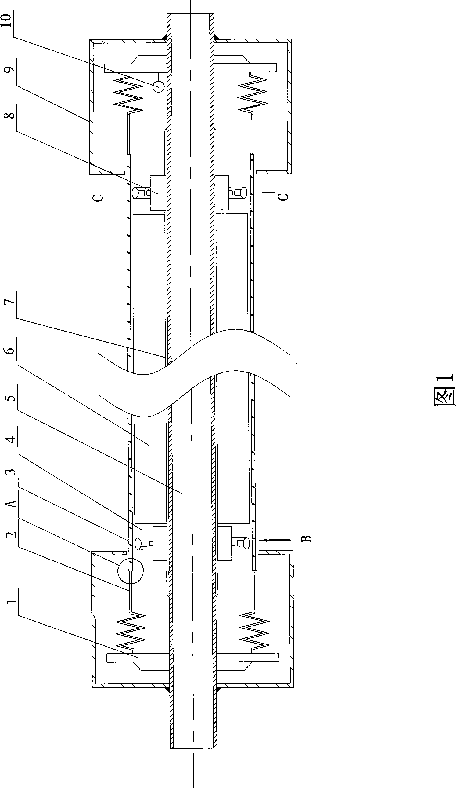
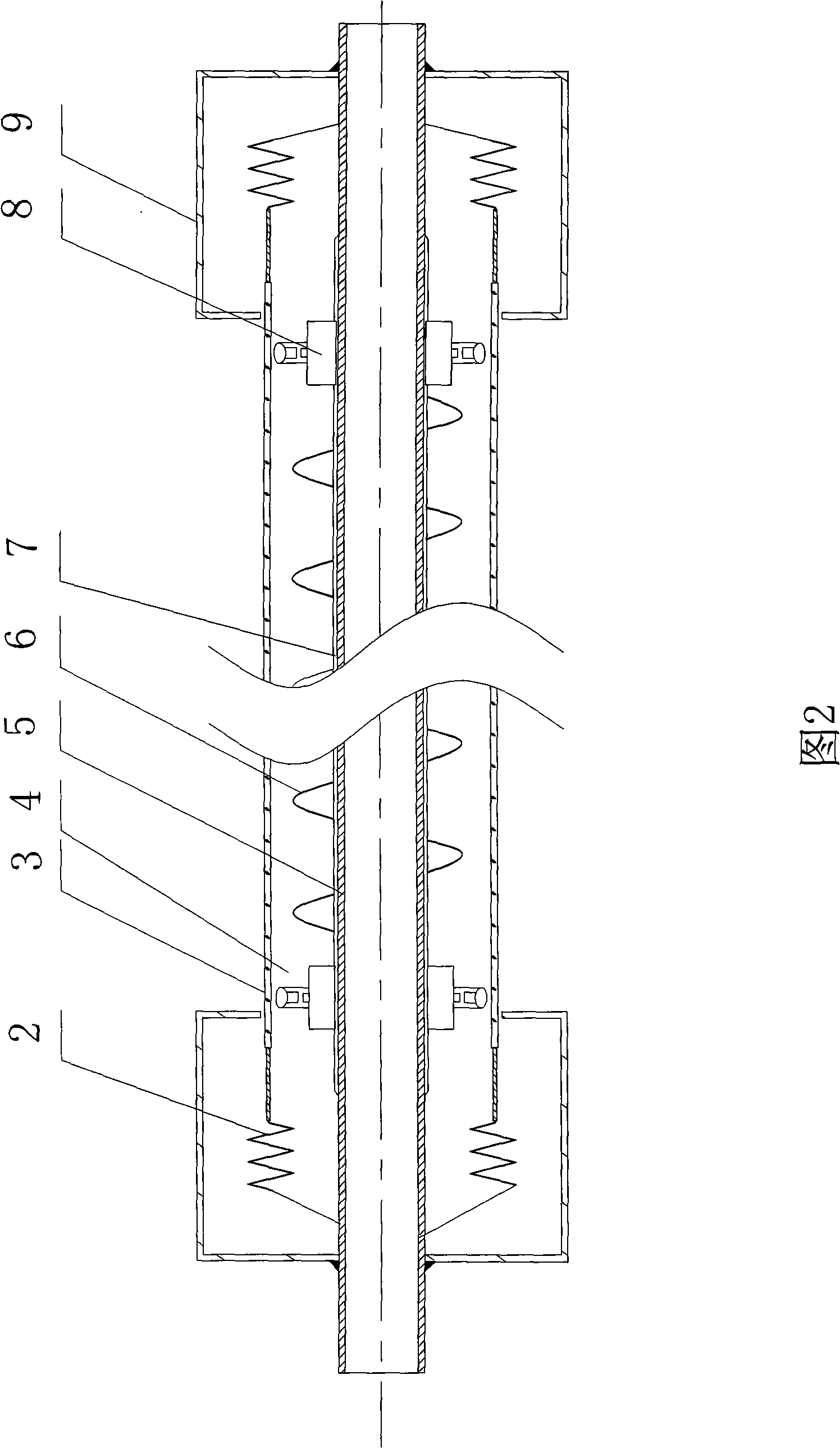
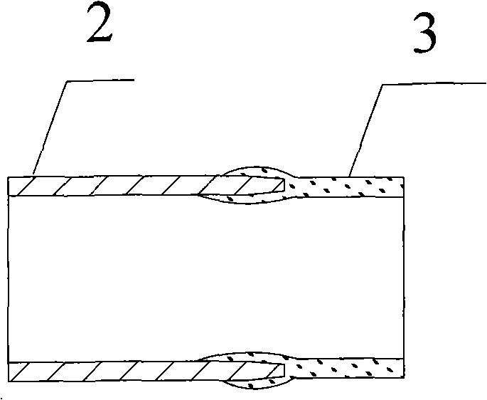
[0018] The vacuum heat collecting tube shown in Figure 1 includes a metal tube 5 covered with a solar absorbing coating 7 on the surface, a glass tube 3 is arranged outside the metal tube 5, and a vacuum layer 4 is formed between the glass tube 3 and the metal tube 5 The getter 10 can be placed in the vacuum layer 4 between the glass tube 3 and the metal tube 5 to maintain the vacuum degree. The two ends of the glass tube 3 are provided with bellows 2, and of course only one end thereof A corrugated tube 2 is provided, one end of the corrugated tube 2 is directly sealed with the glass tube 3, the other end of the corrugated tube 2 is connected with the metal tube 5, the corrugated tube 2 and the metal tube 5 and the corrugated tube 2 and the The interface of the glass tube 3 is respectively equipped with a protective cover 9 to better protect the connection seam. The bellows 2 adopts a linear expansion coefficient of 3×10 -6 m / m·℃ to 5×10 -6 m / m·℃ material, so because the lin...


PUM


Abstract

The invention relates to the solar energy technical field, mainly related to a vacuum tube collector, comprising a metal pipe with the surface coated with a solar energy absorption coating layer, wherein a glass pipe is arranged outside the metal pipe; a vacuum layer is arranged between the glass pipe and the metal pipe, and getter can be put in the vacuum layer between the glass pipe and the metal pipe to maintain the vacuum degree; at least one end of the glass pipe is provided with a corrugated metal pipe, one end of the corrugated metal pipe is directly connected and sealed with the glass pipe, and the other end of the corrugated metal pipe is connected with the metal pipe; the joint between the corrugated metal pipe and the metal pipe and the corrugated metal pipe with the glass pipe are both provided with a shield to better protect the connecting joints. The corrugated pipe is made of material with the linear expansion coefficient between the 3 multiplied by 10<-6> / degrees to 5 multiplied by 10<-6> / degrees. The expansion coefficient is close to that of glass, thereby the corrugated pipe can be directly connected and sealed with the glass pipe arranged outside rather than connected through Kovar, thus reducing the number of the joints, improving the reliability of the pipes and better ensuring the vacuum degree.

Description

technical field [0001] The invention relates to the field of solar heat collecting tubes, and mainly relates to the field of solar heat collecting tubes with bellows. Background technique [0002] At present, domestic glass-metal straight-through solar vacuum heat collection tubes generally use metal tubes covered with solar absorbing coatings, metal tubes with glass tubes, and vacuum pumped between the glass tubes and metal tubes. In order to compensate the expansion of the glass tube smaller than the metal tube after the temperature rises, the bellows are often used to compensate for the expansion difference, and the bellows and the glass are connected by a Kovar alloy transition. [0003] The patent No. ZL 200620075347.3, which was retrieved and published on July 25, 2006, is called the patent of external expansion tank type solar vacuum heat collection tube. The heat collection tube includes a metal tube covered with a solar absorbing coating on the surface, and the meta...

Claims


Application Information

Patent Timeline
IPC IPC(8): F24J2/05F24S10/40
CPCY02E10/44F24J2002/4681F24J2/055F24S10/45F24S2025/6013
Inventor 王军
Owner SOUTHEAST UNIV
Learn More