Constant support

A stable and supportive technology, used in pipeline supports, mining equipment, earth-moving drilling, etc., can solve the problem of difficult operation in the working space, and achieve the effect of enhancing the construction method.

Active Publication Date: 2008-09-24
LISEGA GMBH
View PDF1 Cites 8 Cited by
  • Summary
  • Abstract
  • Description
  • Claims
  • Application Information

AI Technical Summary

Problems solved by technology

In this case, the stabilizing bracket has a relatively high overall height, so that the stabilizing bracket requires a correspondingly large working space between a foundation and the load and is difficult to handle during installation, especially in tight spaces.

Method used


Image

  • Constant support
  • Constant support
  • Constant support

Examples


Embodiment Construction

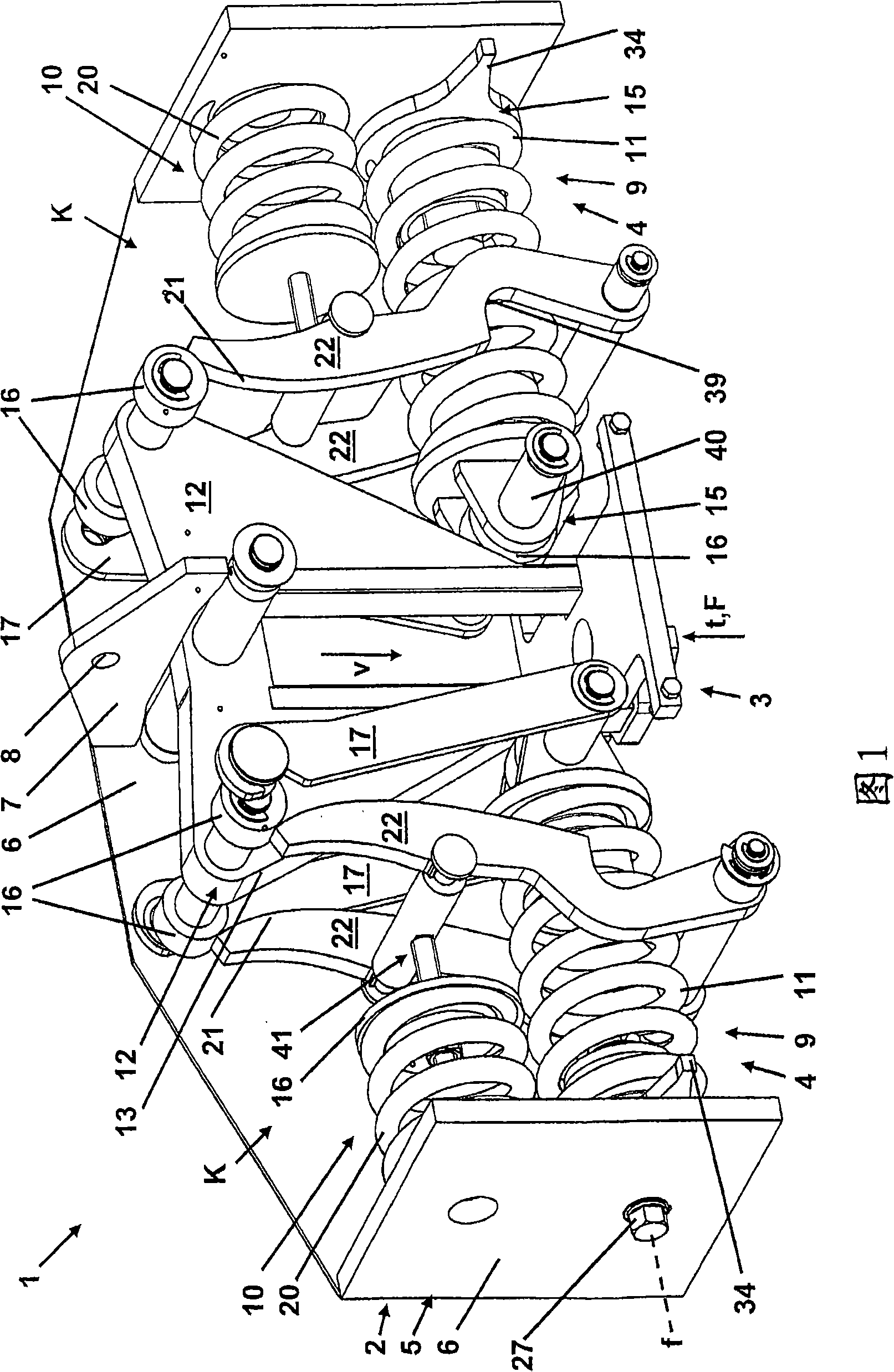
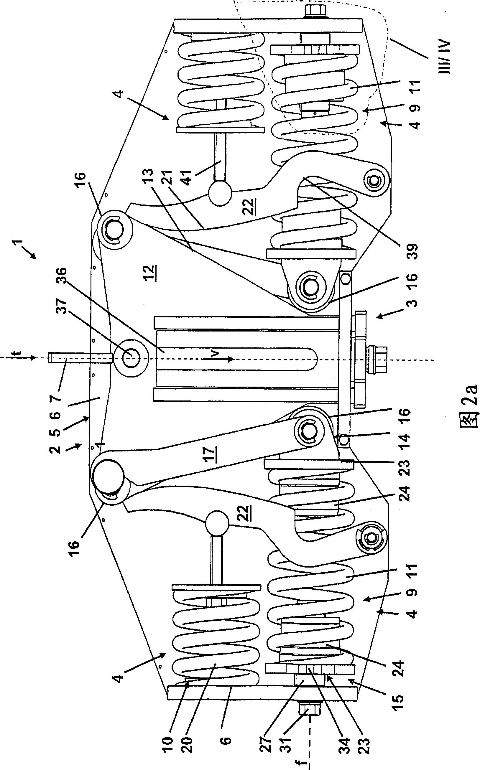
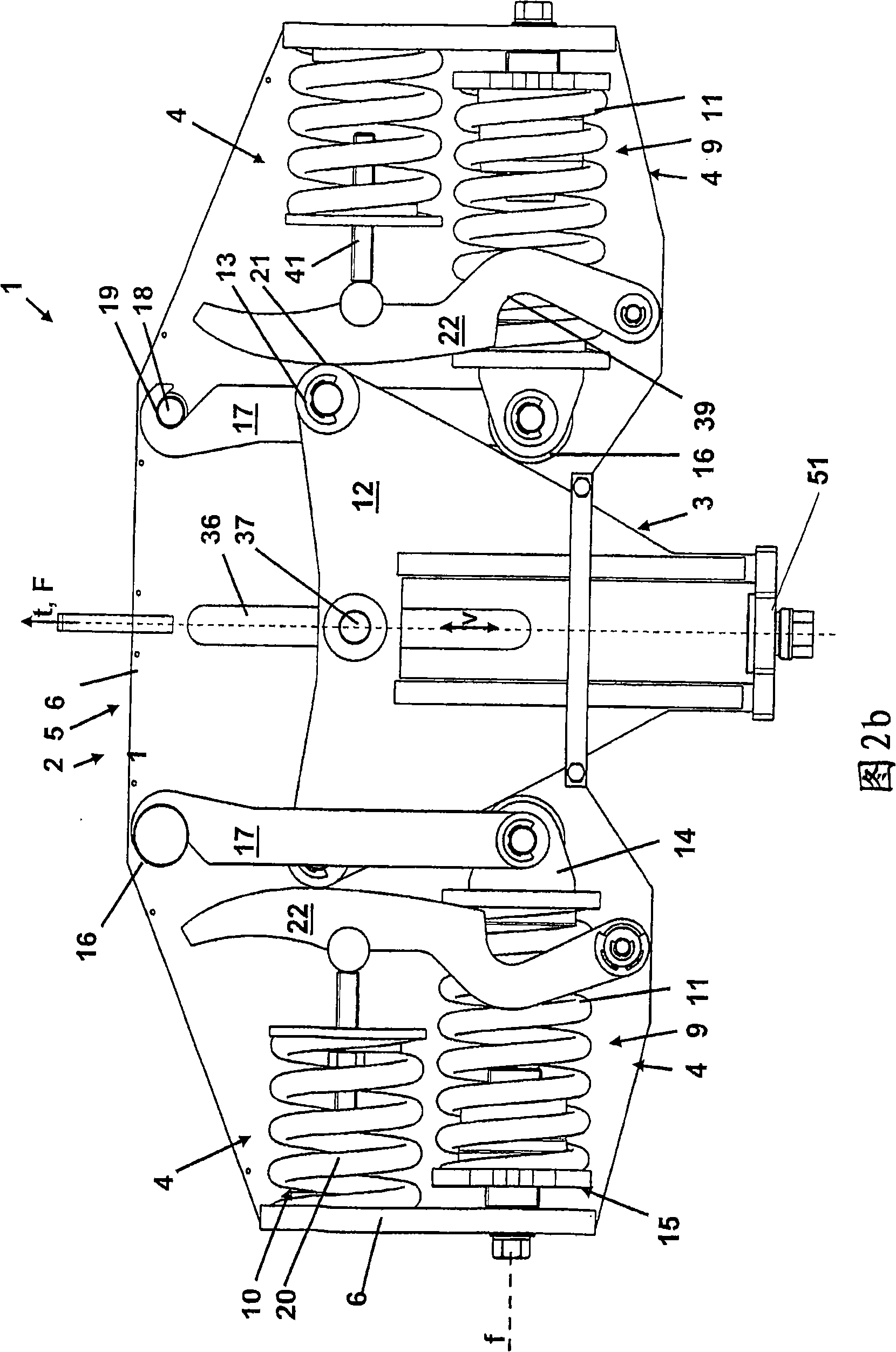
[0059] 1 to 4 show different views of a first embodiment and FIGS. 5 to 8 of a second embodiment of a stabilizing support 1 configured as a stabilizing hanger for use in the drawings. A moving load not shown in the figure, especially for pipes not shown in the figure, etc., comprising a fixed part 2, a load bearing part 3 and a spring system 4 arranged between the fixed part 2 and the load bearing part 3 To create a constant support force. In both embodiments, the spring system each has a compensating device k for compensating the changing pressure of the main spring device 9 .

[0060] In the two embodiments shown in the figures, the stabilizing bracket 1 is designed as a stabilizing hanger, comprising an upper fastening part 2 in the installed position and a downwardly extending load bearing part 3 for suspending loads not shown in the figures. The fastening part 2 has a housing 5 with side walls 6 , the front side walls being omitted in FIGS. 1 to 3 and 5 to 6 for the sake...


PUM


Abstract

The invention relates to a constant support (1) for moving loads, especially pipelines and similar. Said constant support (1) comprises a fastening part (2), a load-bearing part (3), and a spring system (4) which is located between the fastening part (2) and the load-bearing part (3) to generate a constant bearing strength. The spring system (4) is provided with a main spring assembly (9) absorbing the load and a device (K) for compensating changing pressures of the main spring assembly (9).

Description

technical field [0001] The invention relates to a stabilizing support for moving loads, in particular for pipes or the like, comprising a fixed part, a load-bearing part and a spring system arranged between the fixed part and the load-bearing part for producing A constant bearing force is maintained, wherein the spring system has a load-bearing main spring arrangement and an auxiliary spring arrangement for compensating the changing pressure of the main spring arrangement. The fixing part is used to fix the stabilizing bracket on a foundation, and the load supporting part is used to bear the force exerted on the stabilizing bracket by the load. The invention also relates to a stabilizing support with a compensating device. Background technique [0002] An auxiliary spring device is an embodiment of a compensating device which is generally designed to compensate for tension and / or compressive forces of a change in the central position of the main spring device away from the ...

Claims


Application Information

Patent Timeline
Patent Type & Authority Applications(China)
IPC IPC(8): F16L3/205
CPCF16L3/2056F16L3/205E21D5/016
Inventor H-H·哈尔特克
Owner LISEGA GMBH
Why Eureka
Try Eureka