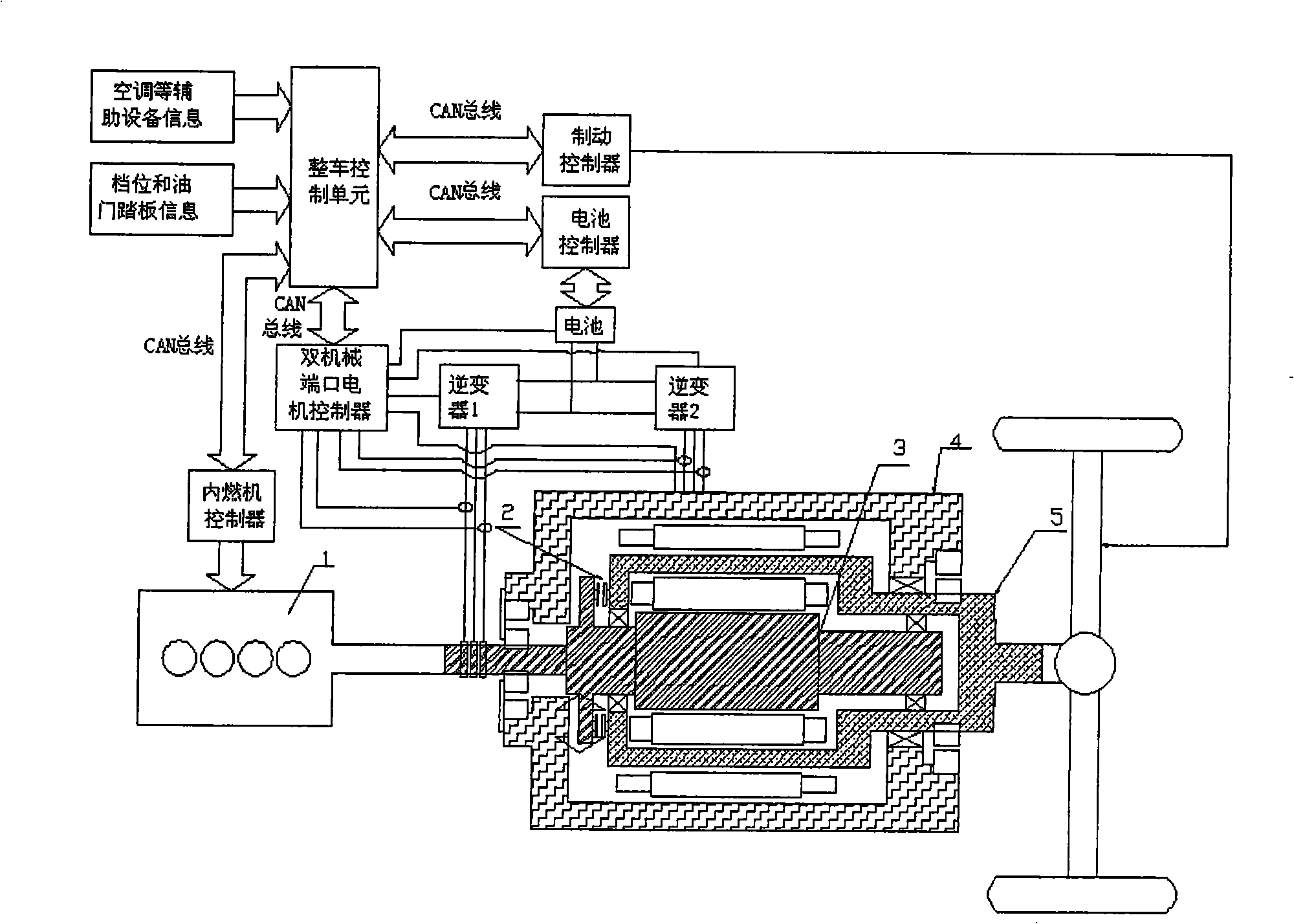
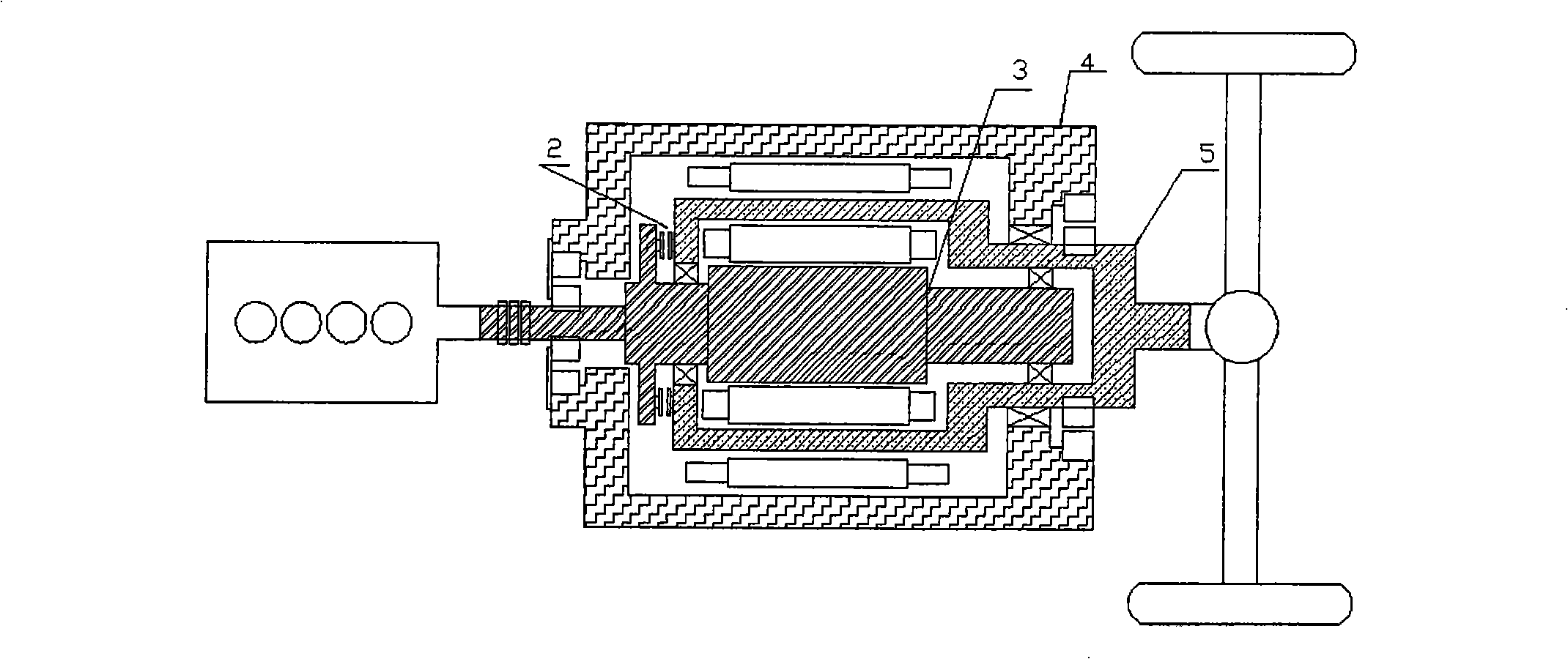
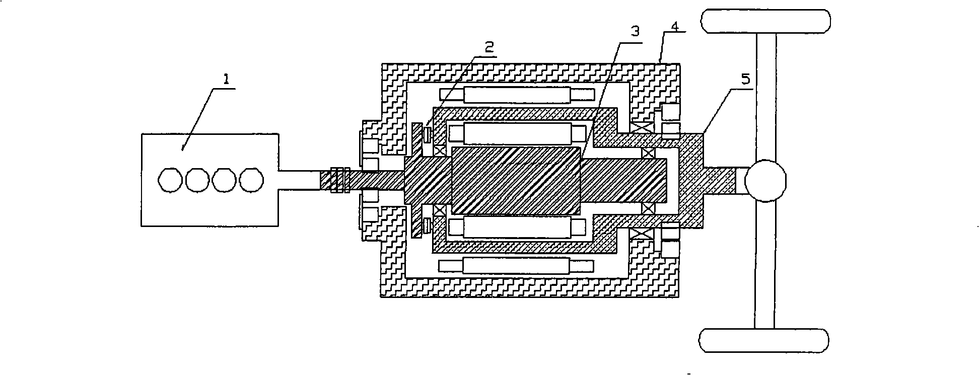
[0041] figure 1 It is the application topology diagram of the dual mechanical port motor of the present invention in a hybrid electric vehicle. Such as figure 1 As shown, a hybrid vehicle equipped with a dual mechanical port motor is mainly composed of two parts: a mechanical body and an electrical control. The dual mechanical port motor is a concentrically arranged three-layer structure, the outermost layer is the stator 4, the middle is the outer rotor 5, and the innermost layer is the inner rotor 3. Among them, armature windings are installed on the stator 4 and the inner rotor 3. The inner rotor current can be passed into the armature winding of the inner rotor 3 from an external power source through brushes and slip rings. The inner rotor and the crankshaft of the internal combustion engine 1 are directly connected to the inner rotor 3 of the dual mechanical port motor, and a clutch 2 is installed between the inner rotor 3 and the outer rotor 5 of the dual mechanical port motor. figure 1 The clutch installation form in is only a schematic diagram, and the actual model and installation position of the clutch can be changed according to actual needs. The current of the armature windings on the inner rotor 3 and the stator 4 of the dual mechanical port motor comes from the inverter 1 and the inverter 2, and the DC power supply of the inverter comes from the battery. The SOC management of the battery state of charge is implemented by the battery control unit. When the dual mechanical port motor controller realizes the dual mechanical port motor control, the outer motor adopts torque control and the inner motor adopts speed control. Therefore, torque and speed signals must be given. The vehicle control unit is based on the vehicle in each working mode. The calculated torque and speed are transmitted to the dual mechanical port motor controller through the CAN bus. The throttle opening signal of the internal combustion engine 1 is controlled by the internal combustion engine controller. The vehicle control unit transmits the calculated torque and speed of the internal combustion engine to the internal combustion engine controller via the CAN bus, and the internal combustion engine converts it into a signal of the opening degree. So as to realize the control of the internal combustion engine 1 and its door opening degree. When the vehicle is braking, the vehicle control unit transmits the braking signal to the braking control unit through the CAN bus, and the braking control unit brakes the vehicle.
[0042] figure 2 It is the topological schematic diagram of the mechanical body of the dual mechanical port motor in the state of separating the clutch in the present invention. Clutch disengagement and lock-up control are divided into the following working conditions: 1. Stop power generation 2. Pure electric reversing and hybrid reversing 3. Pure electric working state 4. Hybrid working state. The specific implementation method is that the dual mechanical port motor controller controls the clutch and the lock according to the control words of the parking power generation, pure electric reversing, hybrid reversing, pure electric, hybrid and high-speed parallel working states transmitted from the CAN bus. When the control word received by the dual mechanical port motor controller is stopping power generation, the corresponding relay is controlled to separate the clutch and the locker; when the control word is pure electric reversing, the corresponding relay is controlled to separate the clutch and the locker ; When the control word is hybrid reversing, control the corresponding relay to separate the clutch and close the lock; when the control word is pure electric, control the corresponding relay to separate the clutch and close the lock; when the control word is hybrid , Control the corresponding relay to separate the clutch and the lock.
[0043] image 3 It is a schematic diagram of the mechanical body topology of the dual mechanical port motor in the closed working state of the clutch in the present invention. When the control word received by the dual mechanical port motor controller is a high-speed parallel operation mode, the corresponding relay is controlled to close the clutch and the lock.
[0044] Figure 4 It is the MAP diagram of the internal combustion engine in the present invention. Such as Figure 4 As shown, when the internal combustion engine 1 works with the constant power curve I and the resistance torque T2, the internal combustion engine 1 will work stably with a certain torque and speed at the intersection point a of the two curves. If the resistance torque changes from T2 to T3 when the car is climbing a slope, the internal combustion engine 1 will automatically adjust and the operating point will transition from point a to point b under the condition that the driver does not intervene or control the internal combustion engine 1. When the speed drops by Δn, the torque increases by ΔT to adapt to changes in external resistance. Similarly, if the resistance torque changes from T2 to T1 when the car is downhill, the internal combustion engine 1 will automatically adjust and the operating point will transition from point a to point c under the condition that the driver does not intervene or control the internal combustion engine 1. At this time, the speed has increased by Δn, and the torque has decreased by ΔT to adapt to changes in external resistance. At the same time, the stable working range of the internal combustion engine 1 must also be restricted, and its working range is from n min To n max , When the working speed of the internal combustion engine 1 is lower than n min When the energy storage of moving parts such as flywheel is small, the fluctuation of the rotation speed of the internal combustion engine 1 is too large, and it cannot operate stably or efficiently; when the working speed of the internal combustion engine 1 is greater than n max , The internal combustion engine 1 cannot operate efficiently due to the increase of inertial force caused by the excessively high speed, the large mechanical loss, the decrease of the charge coefficient, and the deterioration of the working process. According to the aforementioned automatic adjustment performance of the internal combustion engine 1, and the stable operating range of the internal combustion engine 1, the operating point of the internal combustion engine 1 must be controlled. Therefore, in the present invention, the output torque T of the internal combustion engine 1 ice Set to a fixed value on the OOL curve, and the speed ω ice P transmitted by the internal combustion engine control unit according to the vehicle control unit ice decided together, ω ice = P ice T ice .
[0045] Figure 5 It is an output plan view of the whole vehicle as an example of the present invention, such as Figure 5 As shown, the figure includes vehicle drive shaft operating point, engine operating point, engine OOL, resistance torque curve, engine external characteristic curve, external motor maximum output, external motor output range, internal motor output range, and internal motor maximum output. The control at this time is that when the internal combustion engine needs to be started, the internal motor is controlled to bring the internal combustion engine to a certain speed, and then the internal combustion engine is started to output the output torque T of the internal combustion engine. ice Always stay at T given , T given Represents the given torque value; speed ω ice Can start from n 1 To n 2 Change between, here n 1 , N 2 Represents the speed value, speed ω ice P transmitted by the internal combustion engine control unit according to the vehicle control unit ice Decide together, ω ice = P ice T ice . This ensures that the internal combustion engine runs in the best working condition during the entire working process.