Planning method for ion beam polishing path

A polishing path and ion beam technology, applied in the direction of electrical program control, digital control, etc., can solve problems such as long processing time, achieve the effect of improving polishing accuracy and shortening time

Inactive Publication Date: 2008-10-01
NAT UNIV OF DEFENSE TECH
View PDF0 Cites 30 Cited by
  • Summary
  • Abstract
  • Description
  • Claims
  • Application Information

AI Technical Summary

Problems solved by technology

The advantage of the Archimedes spiral is that the spirals are equally spaced in the radial direction, that is, the radial feed is equally spaced during processing, but because the growth rate of the area enclosed by the Archimedes spiral changes, which is dA dθ = 2 π a 2 ( θ - π ) It increases with the increase of the angle, which means that the arc angle corresponding to the unit area surrounded by the helix near the center of the wor

Method used


Image

  • Planning method for ion beam polishing path
  • Planning method for ion beam polishing path
  • Planning method for ion beam polishing path

Examples


Embodiment

[0024] The ion beam polishing process of this embodiment is carried out on an ion beam polishing equipment, and the process parameters are set as follows: the working gas is argon, and the working vacuum is 0.8×10 -2 Pa, ion energy 1100eV, beam current 25mA. The test workpiece to be polished is ordinary glass-ceramics with a diameter of 100mm.

[0025] The ion beam polishing is carried out to the described glass-ceramics by the following method steps:

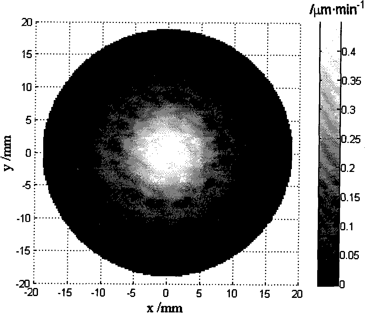
[0026] 1. Determine the removal function: apply the above-mentioned ion beam polishing process to carry out the removal function test, and the obtained removal function is as follows: figure 1 As shown, the diameter of the removal function d=32mm, the volume removal rate v=84μm·mm 2 min -1 ;

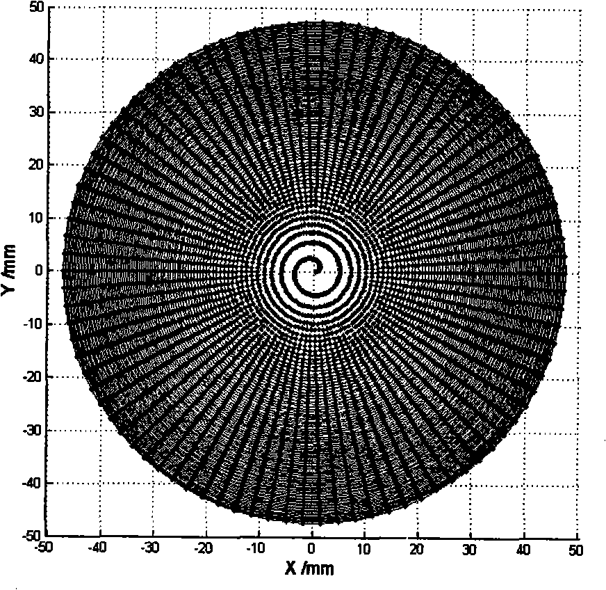
[0027] 2. Establish the polishing path equation: establish the helix equation r=bθ 1 / 2 , where r is the length of the polar axis, θ is the angle of rotation, and b is the helix parameter. Since the removal function diameter d=32mm of...


PUM


Abstract

The invention discloses a method for programming an ion beam polishing path, which comprises the following steps that: first, removing function of polishing technique is determined; the polishing path and processing points on the path are determined according to a proposed helix; distribution data of surface shape errors of optical lens surface to be polished and the removing function of the ion beam polishing which are obtained from detecting are used for calculating density distribution of the staying time in polishing, and the density distribution of the staying time is used for calculating the staying time of each point on the polishing path; finally, coordinates of each point on the polishing path and the staying time of the point are used for polishing the optical lens surface to be polished by the ion beam. The method has the advantages of ensuring that the speed of a rotating shaft of a polishing workpiece maintains constant, weakening the limit of the requirement of maximum rotating speed in processing, shortening processing time and being beneficial to enhancing polishing precision.

Description

technical field [0001] The invention belongs to the field of optical processing, in particular to an ion beam polishing process using a special processing path. Background technique [0002] In the existing ion beam polishing process, there are two basic ways of scanning the ion beam during processing: one is xy linear raster scanning, and the other is ρθ rotary helical scanning. For raster scanning, since the optical element does not perform rotary motion, only the x and y axes move, so raster scanning requires relatively large strokes of the x-axis and y-axis of the processing equipment. It is required that the stroke of the x-axis and y-axis can cover the entire optical mirror surface, and During raster scanning processing, the ion source has to turn around repeatedly, which increases the processing time. On the contrary, due to the rotary motion of the workpiece, the helical scanning reduces the stroke requirements of the x-axis and y-axis, and the ion source performs a...

Claims


Application Information

Patent Timeline
IPC IPC(8): C03C23/00G05B19/19
Inventor 戴一帆李圣怡周林解旭辉彭小强吴宇列王建敏
Owner NAT UNIV OF DEFENSE TECH
Why Eureka
Try Eureka