Multi-insulated sample local discharge test electrode apparatus

A partial discharge and test electrode technology, applied in the direction of material breakdown voltage, etc., can solve the problems of inability to truly simulate partial discharge of power equipment insulation, complex insulation structure of power equipment, inconsistent test conditions, etc., to improve reliability and objectivity, Increase reliability and objectivity, and ensure the effect of not interfering with each other

Inactive Publication Date: 2008-10-01
CHONGQING UNIV
View PDF0 Cites 6 Cited by
  • Summary
  • Abstract
  • Description
  • Claims
  • Application Information

AI Technical Summary

Problems solved by technology

The internal insulation structure of power equipment is complex, and the partial discharge signal is often not the discharge of a single defect type, but the result of the joint action of multiple defect discharges, and the test results obey statistical laws
However, at present, domestic and foreign research institutes generally use a single insulating sample, single defect, and single electric field stress partial discharge model under laboratory conditions when conducting research on partial discharge caused by internal insulation defects in high-voltage power equipment. Realistically simulate the partial discharge phenomenon of the internal insulation of power equipment; some of them also use multiple independent single electrodes to realize it, but there are major problems such as high device cost and inconsistent test conditions (such as stray capacitance)

Method used


Image

  • Multi-insulated sample local discharge test electrode apparatus
  • Multi-insulated sample local discharge test electrode apparatus
  • Multi-insulated sample local discharge test electrode apparatus

Examples


Embodiment Construction

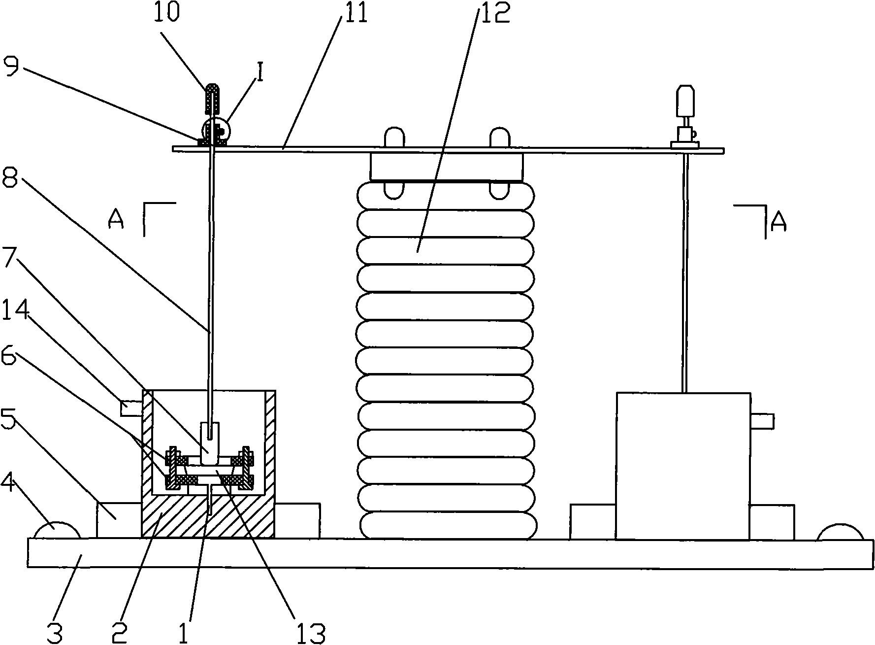
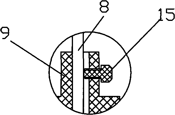
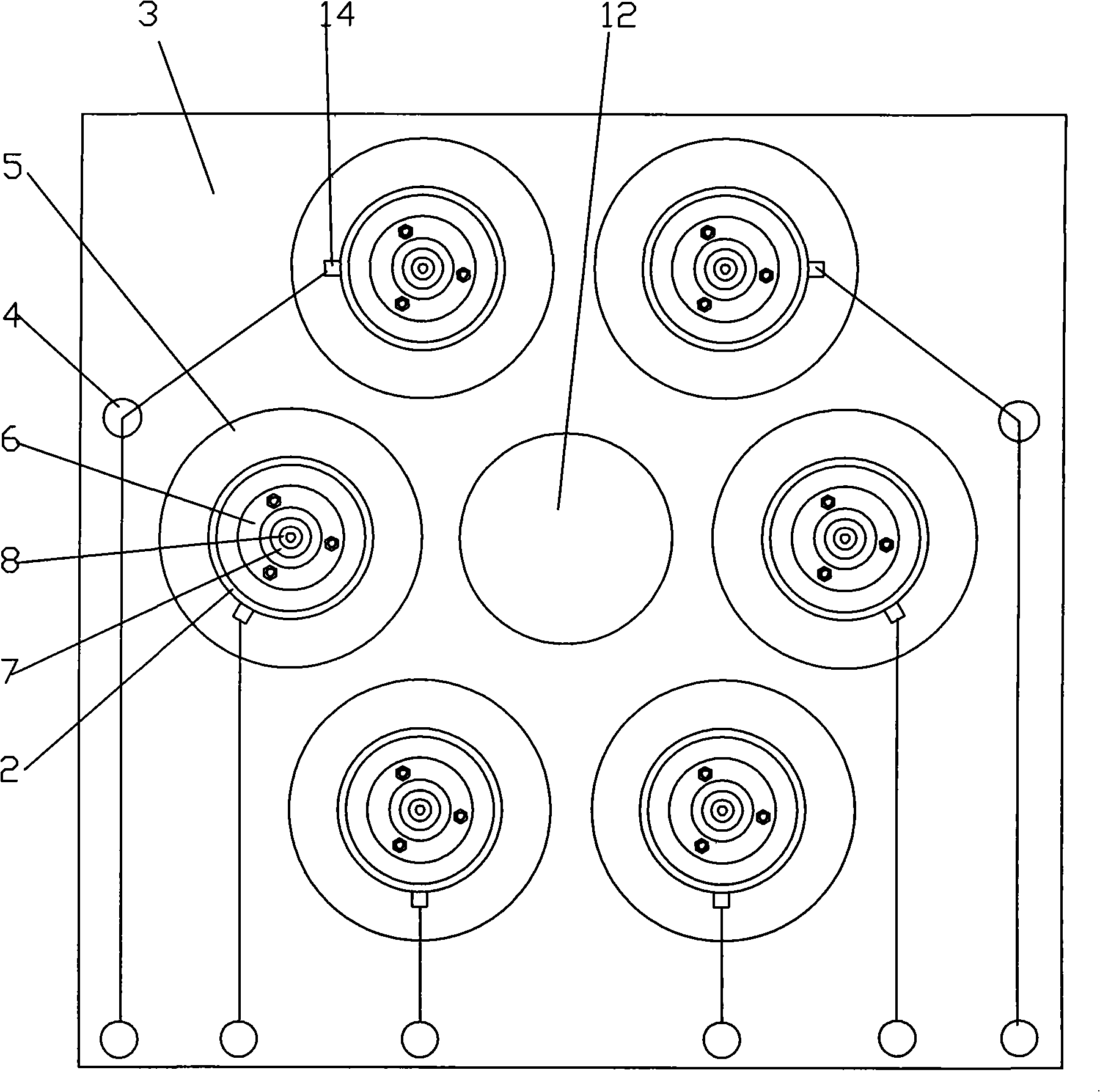
[0020] figure 1 It is a structural schematic diagram of the present invention, figure 2 for figure 1 Enlarged view at I, image 3 for figure 1 A sectional view along A-A, as shown in the figure: the multi-insulation sample partial discharge test electrode device of the present embodiment includes a disc-shaped ground electrode 1, a cylindrical high-voltage electrode 7 and a conductive rod 8 connected with the high-voltage electrode 7, and also includes High-voltage electrode plate 11, post insulator 12 and insulating seat plate 3, one end of post insulator 12 is fixedly connected to high-voltage electrode plate 11, and the other end is fixedly connected to insulating seat plate 3; one end of conductive rod 8 passes through high-voltage electrode plate 11, and the high-voltage electrode plate The upper part of 11 bears a bushing 9, and the conductive rod 8 passes through one end of the upper part of the high-voltage electrode plate 11 to fit through the bushing 9, and a tra...


PUM


Abstract

The present invention discloses a multiple insulation sample partial discharge test electrode device which comprises an earth electrode, a high pressure electrode and a conductive rod connected with the high pressure electrode. The invention also comprises a high pressure electrode plate, a supporting insulator and an insulating base plate. One end of the supporting insulator is permanently connected with the high pressure electrode plate and the other end is permanently connected with the insulating base plate. One end of the conductive rod is permanently connected with the high pressure electrode plate and is conducted, and the other end is connected with the high pressure electrode and is conducted. The high pressure electrode is arranged at the upper part of the insulator to be measured. The insulator to be measured contacts the earth electrode. The number of conductive rods, high pressure electrodes and earth electrodes are at least two respectively and these components are arranged at the circumference of the supporting insulator with one-to-one correspondence. The invention can simulate various typical single defect or mixed defect at the inner part of the high pressure electric power equipment. The characteristics of partial discharge signals which are generated simultaneously by a plurality of insulation samples or a plurality of insulation defects are obtained. The reliability and objectivity for on-line monitoring the inner insulation defect of the electric power device is increased.

Description

technical field [0001] The invention relates to an insulating sample partial discharge test electrode, in particular to a multi-insulation sample partial discharge test electrode device for simulating internal insulation defects of high-voltage power equipment. Background technique [0002] Insulation defects are the main cause of insulation accidents in high-voltage power equipment. The method of extracting characteristic information of partial discharge is usually used to identify the types of insulation defects inside power equipment, so as to monitor, identify and formulate maintenance measures. The internal insulation structure of power equipment is complex, and the partial discharge signal often does not originate from the discharge of a single defect type, but the result of the joint action of multiple defect discharges, and the test results obey statistical laws. However, at present, domestic and foreign research institutes generally use a single insulating sample, s...

Claims


Application Information

Patent Timeline
Patent Type & Authority Applications(China)
IPC IPC(8): G01N27/92
Inventor 杨丽君廖瑞金王有元杜林向彬
Owner CHONGQING UNIV
Why Eureka
Try Eureka