Diffusing plate

A technology of diffuser plate and reflective layer, applied in the field of diffuser plate, to achieve the effect of uniform brightness

Active Publication Date: 2012-03-14
ENTIRE TECH CO LTD
View PDF0 Cites 0 Cited by
  • Summary
  • Abstract
  • Description
  • Claims
  • Application Information

AI Technical Summary

Problems solved by technology

[0007]However, the top 234a of the microstructure 234 often cannot form a pointed shape, and usually presents a certain curvature
Therefore, when the light 13 is emitted to the top 234a, the total reflection cannot be generated because the incident angle θ3 is too small. mixed, thereby reducing the light diffusion effect of the diffusion plate 230

Method used


Image

  • Diffusing plate
  • Diffusing plate
  • Diffusing plate

Examples


Embodiment Construction

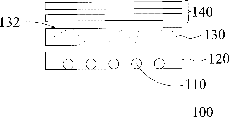
[0040] See Figure 4 , Figure 4 Shown is a backlight module of this embodiment. The backlight module 300 includes a light-emitting source 310, a reflective cover 320, a diffuser 330, and a plurality of optical films 340. The light-emitting source 310 is a cold cathode fluorescent tube in this embodiment. Of course, those of ordinary skill in the art can also use light-emitting diodes ( LED) to replace cold cathode fluorescent tubes. The reflector 320 has light-reflecting properties, and the diffuser plate 330 is made of a polymer light-transmitting material. The polymer light-transmitting material is, for example, polymethyl methacrylate (PMMA) or polymethylmethacrylate. Styrene (Poly Styrene, referred to as PS). In addition, the inside of the diffusion plate 330 may be doped with light diffusion particles or ultraviolet absorbers, for example. The optical film 340 is, for example, a Brightness Enhancement Film or a Diffusion Film. The function of the Brightness Enhancement ...


PUM

PropertyMeasurementUnit
reflectanceaaaaaaaaaa

Abstract

The present invention provides a diffusion plate and a method for coating a reflection layer on the diffusion plate. The diffusion plate is provided with a light-outing surface and a light-entering surface. The light-outing surface is provided with a plurality of microstructure bodies, wherein the top of these microstructure bodies or the bottom dent between the top and each microstructure body is coated with a reflection layer. The method for coating the reflection layer on the diffusion board comprises the following procedures: (a) preparing a slurry containing a reflection material; (b) coating the slurry on the top of the microstructure body or simultaneously coating the slurry on the bottom dent between the top and each microstructure body; (c) drying the slurry coated on the top; and (d) hardening the dried slurry to form a reflection layer.

Description

technical field [0001] The invention relates to an optical diffusion plate, in particular to a diffusion plate with a plurality of microstructures and coated with a reflective layer. Background technique [0002] In recent years, traditional cathode ray tube displays (commonly known as CRT displays) have been gradually replaced by liquid crystal displays. The main reason is that the amount of radiation emitted by liquid crystal displays is much smaller than that of CRT displays. Manufacturing costs are also significantly reduced. Generally speaking, a liquid crystal display includes a backlight module and a liquid crystal panel. The main function of the backlight module is to provide a light source for the liquid crystal display. [0003] Please refer to figure 1 , figure 1 What is shown is an existing backlight module. The backlight module 100 is mainly composed of a cold cathode fluorescent lamp (CCFL) 110, a reflector 120, a diffuser plate 130, and a plurality of o...

Claims


Application Information

Patent Timeline
Patent Type & Authority Patents(China)
IPC IPC(8): G02B5/02G02B1/10
Inventor 郑文峰李振生林昭颖
Owner ENTIRE TECH CO LTD
Why Eureka
Try Eureka