
Workpiece reference point detection method and process apparatus using same

A processing device and detection method technology, which is applied in the direction of measuring devices, metal processing equipment, metal processing machinery parts, etc., can solve the problems of multi-time, edge position detection accuracy, increasing the number of multiple coordinate data, etc.

Inactive Publication Date: 2008-10-01
JTEKT CORP
View PDF1 Cites 7 Cited by
  • Summary
  • Abstract
  • Description
  • Claims
  • Application Information

AI Technical Summary

Problems solved by technology

[0006] In order to detect the edge of the workpiece, in the reference point detection device described in the above-mentioned Patent Document 1, the contact point is estimated based on a plurality of coordinate data of the scanning trajectory when the stylus scans on the non-measurement surface, and the radius of the tip of the stylus. point coordinates, and detect the edge position of the object from the estimated density of contact point coordinates, so the shape of the edge portion, such as the rounded shape and size formed on the edge portion, will give the edge position The detection accuracy has a great influence
In addition, in order to improve the detection accuracy of the edge position, it is necessary to increase the number of coordinate data in the scanning trajectory, so that it will take a lot of time to obtain the coordinate data and estimate the contact point coordinates.

Method used


Image

  • Workpiece reference point detection method and process apparatus using same
  • Workpiece reference point detection method and process apparatus using same
  • Workpiece reference point detection method and process apparatus using same

Examples


Embodiment Construction

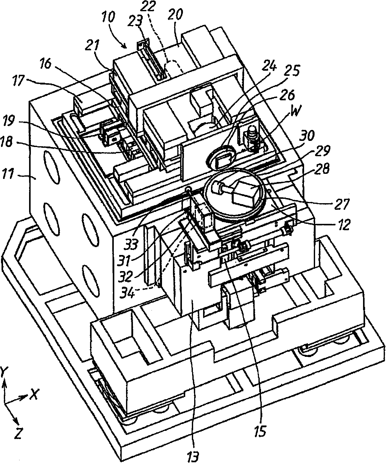
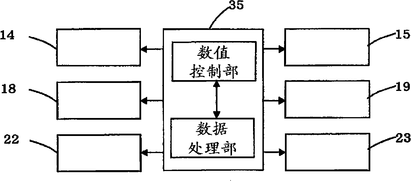
[0032] Hereinafter, a workpiece reference point detection method according to an embodiment of the present invention and a processing apparatus using the method will be described based on the drawings. exist figure 1 Among them, the Y-axis slide table 12 is erected in front of the head 11 of the ultra-precision machining device 10 so that it can move linearly in the vertical Y-axis direction through the guide mechanism 13 . The Y-axis slide table 12 utilizes a linear motor 14 (refer to figure 2 ) moves linearly along the Y-axis direction, and detects the amount of movement through the linear displacement sensor 15, so as to obtain feedback for position control.

[0033] The X-axis slide table 16 is erected on the horizontal surface of the head 11 so as to be linearly movable in the left and right X-axis directions through the guide mechanism 17 . The X-axis slide table 16 linearly moves along the X-axis direction by a linear motor 18 , and detects the movement amount by a ...


PUM


Abstract

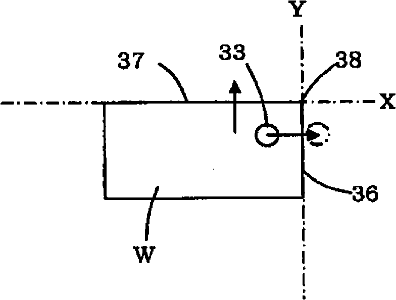
The invention provides a work piece reference point detection method which can make use of a measuring means to high-accuracy detect the reference point, namely a work piece lip, in short time on an organism, and a processing device using the method. A work piece support station and a tool station are relative moved. A probe of the measuring means is connected with the work piece and overcomes spring force to back up. The work piece support station and the tool station are relative moved in scanning speed in the direction of X axis or Y axis. The probe is separated from the work piece lip. When the speed that the probe is separated from the work piece lip to move forward in the direction of Z axis reaches to regular speed, a position detection device detects a relative position of the work piece support station and the tool station. The invention detects out the work piece lip as the reference point on the base of the detected relative position in the direction of X axis or Y axis and a modification distance of the relative move of the work piece support station and the tool station in a period from that the probe is uniform with the work piece lip to the speed that the probe is separated from the work piece lip to move forward reaches the regular speed.

Description

technical field [0001] The present invention relates to a workpiece reference point detection method using a measuring device to detect a workpiece reference point on a machine body, and a processing device using the method to detect a workpiece reference point on a machine body through a detector. Background technique [0002] Conventionally, for a stylus-type shape measuring machine, Patent Document 1 discloses a stylus-type shape measuring machine including: a stylus tip whose cross-sectional shape has an arc shape; The scanning mechanism for contact scanning of the measured surface, the unit for measuring the coordinate data of the scanning trajectory, and the calculation and processing unit for numerical data, wherein the calculation and processing unit estimates the contact according to the plurality of coordinate data of the scanning trajectory and the radius of the front end of the stylus. point coordinates, and detect the edge position of the measured object based o...

Claims


Application Information

Patent Timeline
Patent Type & Authority Applications(China)
IPC IPC(8): G05B19/402G01B21/20
CPCB23Q17/20B23Q17/22B23Q17/2233G05B19/401G05B19/404
Inventor 松本崇山本吉二冲田俊之
Owner JTEKT CORP
Learn More