
Winding machine for nickel-hydrogen battery

A technology of nickel-hydrogen battery and winding machine, which is applied in the direction of alkaline storage battery, alkaline storage battery manufacturing, sustainable manufacturing/processing, etc. unevenness etc.

Inactive Publication Date: 2008-10-01
扬州众力电源设备制造有限公司
View PDF0 Cites 6 Cited by
  • Summary
  • Abstract
  • Description
  • Claims
  • Application Information

AI Technical Summary

Problems solved by technology

[0002] The traditional nickel-hydrogen battery winding machine includes a frame and an equipment substrate fixed on the frame. The equipment substrate is equipped with a battery plate seat, a diaphragm seat, a diaphragm shaft, a plate guide mechanism and a needle rolling mechanism. The center hole of the diaphragm seat is pierced, and the diaphragm is placed on the diaphragm seat. During the winding process, the inner and outer tightness of the wound cell is inconsistent, and the battery’s electro-hydraulic distribution is uneven in the later stage, and the end surface of the cell is uneven. The product quality is directly affected by man-made. Factors have great influence
Although the lithium-ion battery winding machines currently on the market have a diaphragm tension mechanism, the tension of the diaphragm is uneven, and there is no winding and pressing mechanism, diaphragm grabbing mechanism and retractable plate guide mechanism. , The diaphragm is thick, and the winding of the battery must be completed under a certain pressure. Therefore, the current lithium-ion battery winding machine is not suitable for winding nickel-hydrogen power batteries.

Method used


Image

  • Winding machine for nickel-hydrogen battery
  • Winding machine for nickel-hydrogen battery
  • Winding machine for nickel-hydrogen battery

Examples


Embodiment Construction

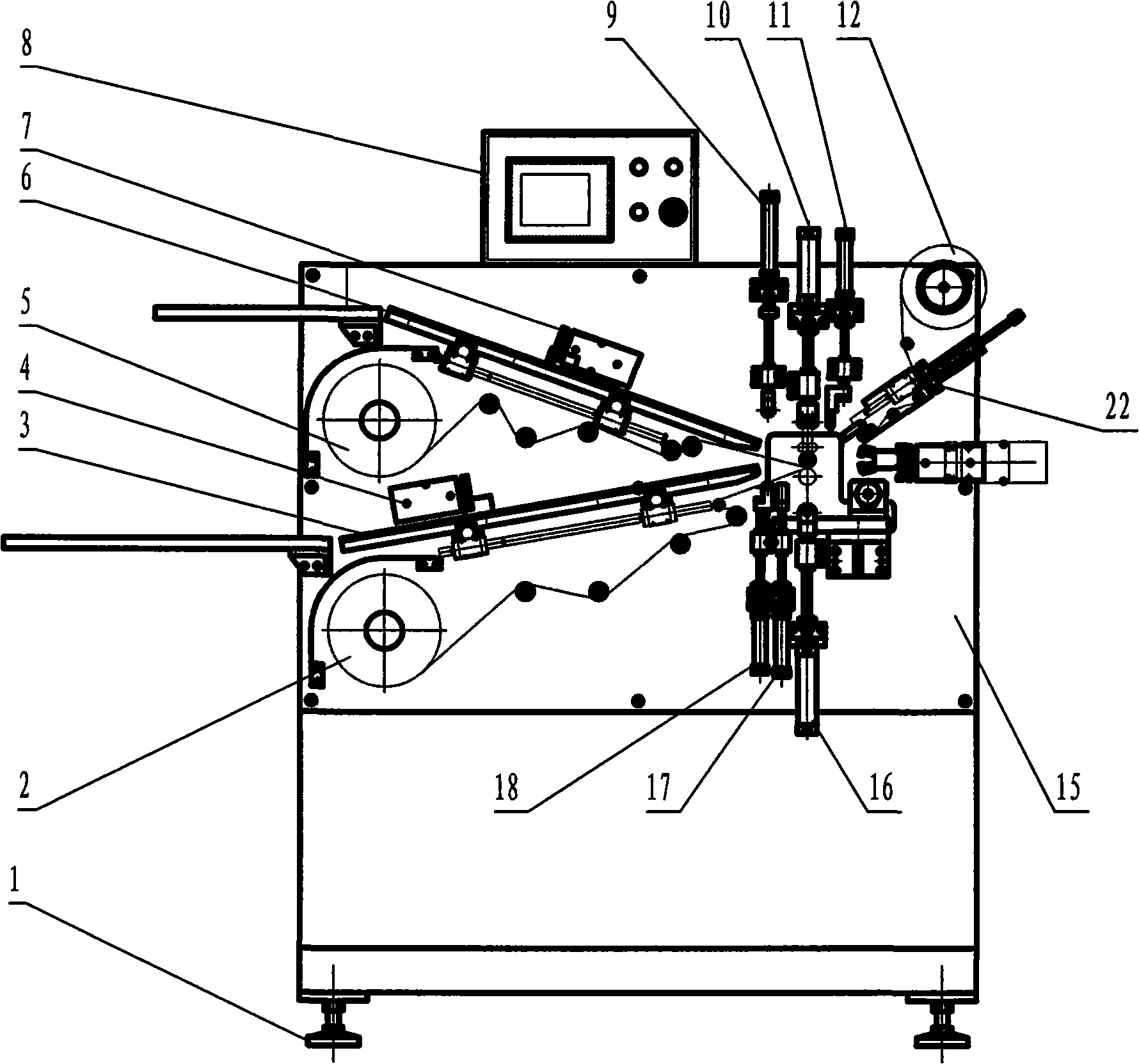
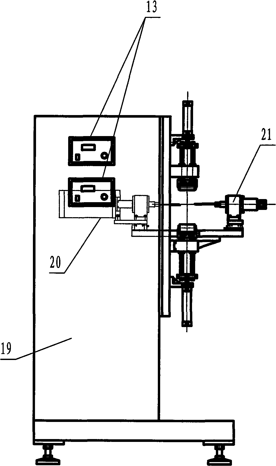
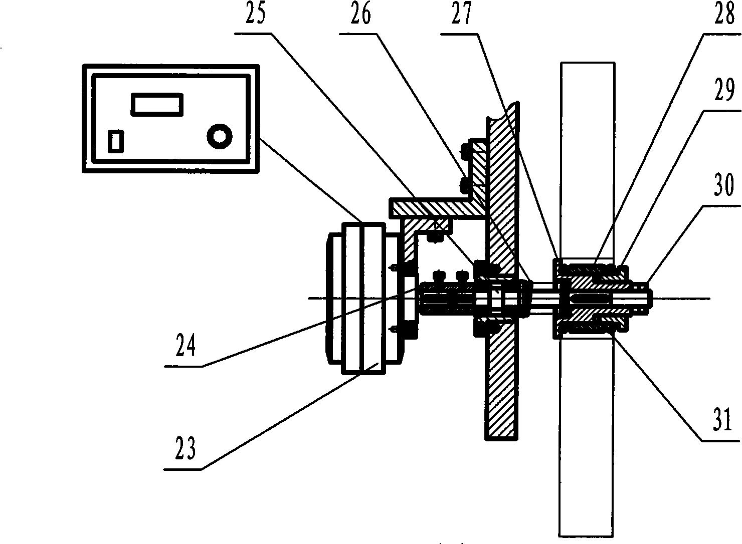
[0018] Such as figure 1 and figure 2 As shown, the nickel-hydrogen battery winding machine of the present invention includes a frame 19 and an equipment substrate 15 fixed on the frame 19. The base of the frame 19 is provided with adjustable feet 1 to adjust the horizontal state of the equipment. The device substrate 15 is provided with a battery plate seat, a diaphragm seat 27, a plate guide mechanism 3, a needle winding mechanism, a diaphragm constant tension control mechanism, a winding constant pressure control mechanism, and a diaphragm grasping mechanism.

[0019] The winding upper pressing mechanism 10, the winding lower pressing mechanism 16, the main needle winding mechanism 20, and the auxiliary needle winding mechanism 21 wind the positive and negative plates and the positive and negative diaphragms into winding batteries 35 according to the battery process requirements; Diaphragm roll 2, positive diaphragm roll 5, upper diaphragm mechanism 9, lower diaphragm mech...


PUM


Abstract

The invention discloses a constant force coiling machine for MH-Ni dynamic cylinder battery coiling, comprising a frame and a device baseplate provided with a battery pole plate base, a membrane base, a pole plate guiding mechanism and a pin mechanism. The device controls a magnetic powder brake by membrane tension to realize membrane constant tension control, controls the coiling compressing mechanism by PLC to realize constant tension coiling and adopts the telescopic pole plate guiding mechanism to ensure flatness of an core end surface of the coiling as well as arranges a membrane grasping mechanism to realize an automatic feed in of a positive and a negative membrane. In the coiling process, under a circumstance that a diameter of the core of the coiling ranges up and down and degrees of tightness of the coiling core in and out are consistent, the constant force coiling machine, is flat at the end surface and low labor intensity in the operation personnel and great in product quality.

Description

technical field [0001] The invention relates to battery manufacturing equipment, in particular to a winding machine for nickel-hydrogen power cylinder batteries. Background technique [0002] The traditional nickel-hydrogen battery winding machine includes a frame and an equipment substrate fixed on the frame. The equipment substrate is equipped with a battery plate seat, a diaphragm seat, a diaphragm shaft, a plate guide mechanism and a needle rolling mechanism. The center hole of the diaphragm seat is pierced, and the diaphragm is placed on the diaphragm seat. During the winding process, the inner and outer tightness of the wound cell is inconsistent, and the battery’s electro-hydraulic distribution is uneven in the later stage, and the end surface of the cell is uneven. The product quality is directly affected by man-made. Factors have great influence. Although the lithium-ion battery winding machines currently on the market have a diaphragm tension mechanism, the tensio...

Claims


Application Information

Patent Timeline
Patent Type & Authority Applications(China)
IPC IPC(8): H01M10/28
CPCY02E60/124Y02E60/10Y02P70/50
Inventor 徐方林冯营会吴建波
Owner 扬州众力电源设备制造有限公司
Learn More