Method for regulating static reactive compensator of power transmission system
A technology for static reactive power compensation and power transmission system, which is applied in flexible AC power transmission systems, reactive power adjustment/elimination/compensation, etc. problem, to reduce mutual influence and suppress power oscillation
- Summary
- Abstract
- Description
- Claims
- Application Information
AI Technical Summary
Problems solved by technology
Method used
Image

Examples
Embodiment Construction
[0034] A detailed description will be given below in conjunction with the accompanying drawings and specific embodiments of the present invention.
[0035] The embodiments of the present invention specifically include the following steps:
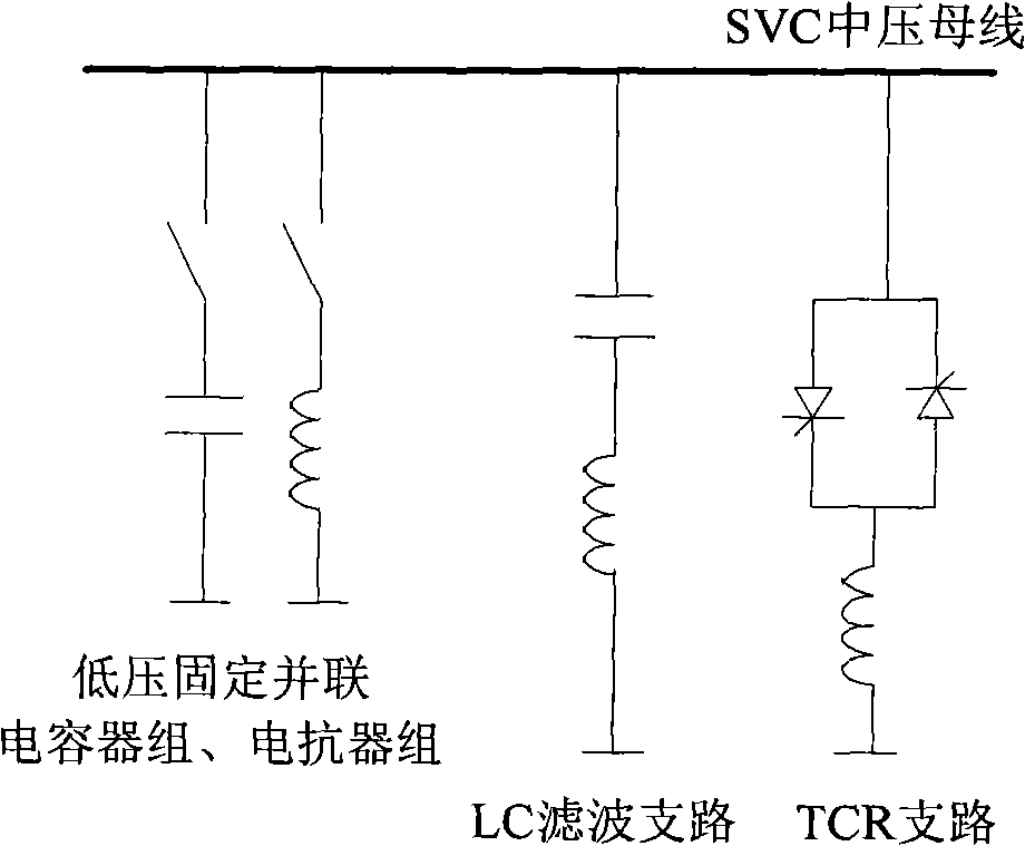
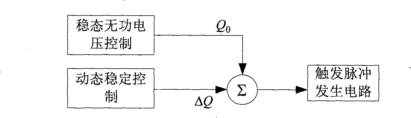
[0036] Step 1. In order to realize the steady-state reactive voltage control, according to the current operating voltage of the transmission system, the reactive power output Q of the TCR branch is obtained 0 ,;
[0037] The step 1 specifically includes:
[0038] Step 11, calculating the average operating voltage of the power transmission system in a long operating period (for example, setting 20 minutes);
[0039] Step 12, judging whether the average operating voltage exceeds the qualified range of the voltage to be controlled, if so, calculating the voltage difference between the average operating voltage and the qualified range of the voltage to be controlled, otherwise, the process ends;
[0040] Step 13, determining the steady-state...
PUM
 Abstract
Description
Claims
Application Information
 - R&D
- Intellectual Property
- Life Sciences
- Materials
- Tech Scout
- Unparalleled Data Quality
- Higher Quality Content
- 60% Fewer Hallucinations
Browse by: Latest US Patents, China's latest patents, Technical Efficacy Thesaurus, Application Domain, Technology Topic, Popular Technical Reports.
© 2025 PatSnap. All rights reserved.Legal|Privacy policy|Modern Slavery Act Transparency Statement|Sitemap|About US| Contact US: help@patsnap.com