Cooling device

A heat dissipation device and heat dissipation fin technology, which can be used in cooling/ventilation/heating transformation, electrical components, electric solid devices, etc., can solve problems such as unsatisfactory functions, and achieve the effect of improving heat dissipation performance and reducing costs

Inactive Publication Date: 2010-05-26
FU ZHUN PRECISION IND SHENZHEN +1
View PDF3 Cites 0 Cited by
  • Summary
  • Abstract
  • Description
  • Claims
  • Application Information

AI Technical Summary

Problems solved by technology

Usually, the heat dissipation capacity of the heat sink is improved by increasing the number of heat pipes, but due to the shape of the heat pipes and the arrangement of the heat sink, the effect is not ideal.

Method used


Image

  • Cooling device
  • Cooling device
  • Cooling device

Examples


Embodiment Construction

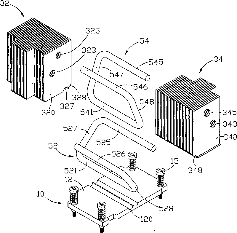
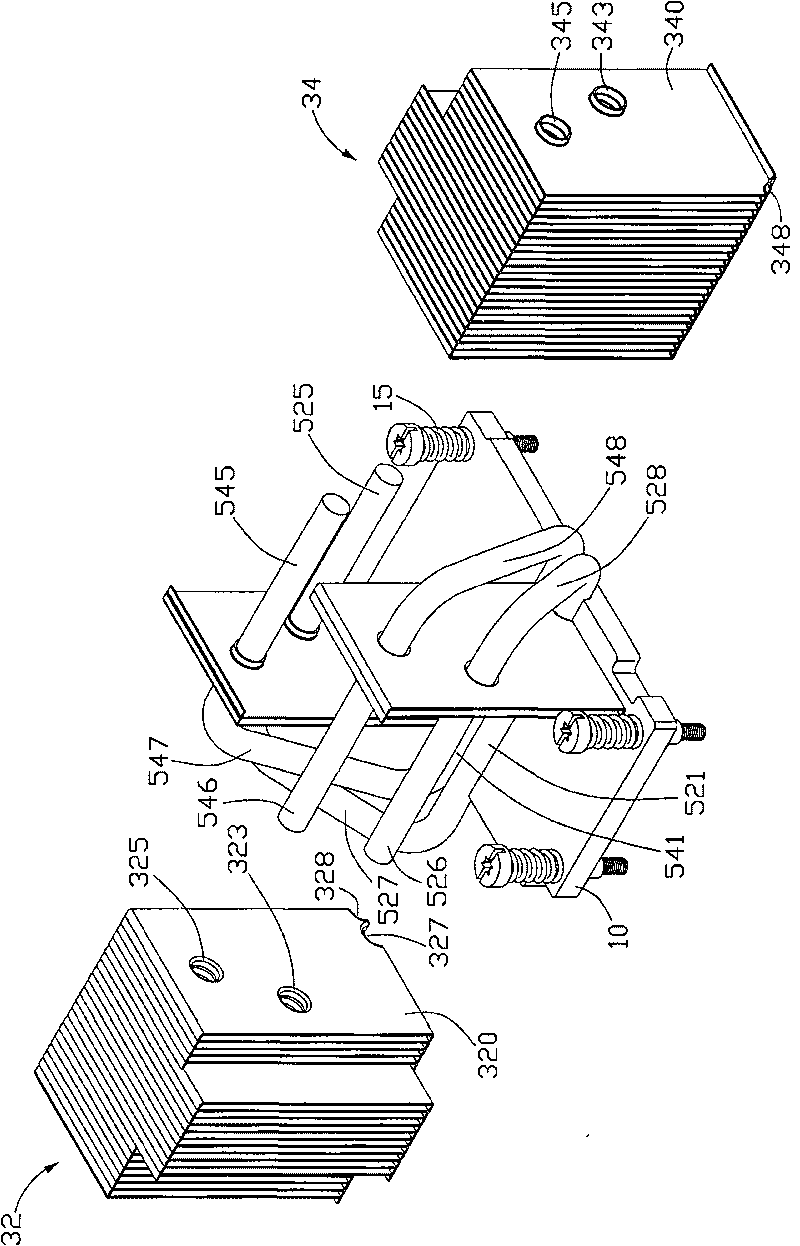
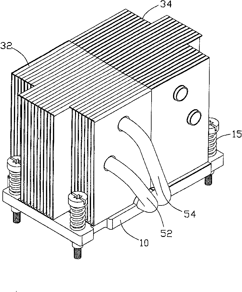
[0011] see figure 1 The heat dissipation device of the present invention includes a base plate 10, a first fin group 32 placed on the base plate 10, a second fin group 34, and two fin groups connecting the base plate 10 and the first and second fin groups 32, 34. Heat pipes 52,54.

[0012] The bottom plate 10 is a roughly rectangular metal plate with good thermal conductivity, such as a copper plate, an aluminum plate, and the like. The lower surface (not shown) of the bottom plate 10 is used to contact the electronic components (not shown) on a circuit board (not shown), and the upper surface of the bottom plate 10 is provided with two parallel adjacent grooves 120 to combine Heat pipes 52,54. Four screws 15 are passed through the four corners of the bottom plate 10 to fix the heat sink on the circuit board where the electronic components are located.

[0013] Two corners of the first cooling fin set 32 ​​close to the screw 15 are cut off to form a receiving space (not sho...


PUM


Abstract

The present invention provides a heat sink for dissipation of electronic elements, including a baseboard, a plurality of dissipation fins mounted on the baseboard and at least a heating tube connecting the baseboard and the fins, the heating tube includes an absorbing segment combined to the baseboard, two dissipating segment combined with the fins and two connecting segments connecting the absorbing segment and corresponding dissipating segment, the dissipating segment is parallel to the absorbing segment and extends to the opposite direction. The dissipating device widely, evenly transmits the energy to the dissipating fins by a few heating tubes, the heat dissipation performance of the dissipating device is enhanced, and the cost of the dissipating device is reduced.

Description

technical field [0001] The invention relates to a heat dissipation device, in particular to a heat dissipation device for heat dissipation of electronic components. Background technique [0002] Electronic components, such as central processing units, generate a lot of heat during operation. In order to ensure the normal operation of electronic components, the heat generated must be dissipated in time. Usually, a heat dissipation device is installed on the electronic component. [0003] A common heat dissipation device includes a metal base plate and a plurality of heat dissipation fins extending from the base plate. The bottom plate is attached to the heat-generating electronic components to absorb the heat generated by them, and then transfer the heat to the fins to dissipate the heat to the surrounding space. However, with the development of the electronic industry, the operating frequency and functions of electronic components are increasing day by day, and their heat ...

Claims


Application Information

Patent Timeline
Patent Type & Authority Patents(China)
IPC IPC(8): H05K7/20H01L23/427
Inventor 郑东波曹磊符猛陈俊吉
Owner FU ZHUN PRECISION IND SHENZHEN
Why Eureka
Try Eureka