Lattice pillar component and mounting method thereof

A lattice column and component technology, applied in the directions of columns, piers, pillars, etc., can solve the problems of insufficient installation strength, large overall deformation, rotation and torsion of lattice columns, and achieves reduction of overlapping vacancies, no welding deformation, The effect of reducing disturbance

Active Publication Date: 2010-06-16
GUANGZHOU CONSTR ENG +1
View PDF4 Cites 2 Cited by
  • Summary
  • Abstract
  • Description
  • Claims
  • Application Information

AI Technical Summary

Problems solved by technology

The bottom locator 15 of this lattice column should be installed before the final setting of the pile core concrete 18 for the first pouring, which is not conducive to the accurate positioning of the locator, and the concrete is not solidified when the locator 15 is installed, and the installation strength is insufficient. The operating space is narrow, and it is easy to cause too much disturbance to the pile core and cannot be accurately positioned; the lattice column is a permanent load-bearing member welded together by steel plate and angle steel. It is supported by a steel bar 13 welded to the lattice column, which is not conducive to ensuring the verticality of the lattice column during hoisting. In addition, the four-corner traction and fixing method of the top positioner 16 is likely to cause the rotation and twist of the lattice column. Unfavorable; In order to increase the strength and rigidity, the past practice is that the lattice column corner column is formed by stacking and welding two angle steels 12, but the welding position overlaps a large space, which needs to be welded and reinforced. After welding, the overall deformation is large and the overall rigidity Insufficient, does not meet the actual construction needs

Method used


Image

  • Lattice pillar component and mounting method thereof
  • Lattice pillar component and mounting method thereof
  • Lattice pillar component and mounting method thereof

Examples


Embodiment Construction

[0033] The present invention will be described in further detail below in conjunction with the accompanying drawings and embodiments.

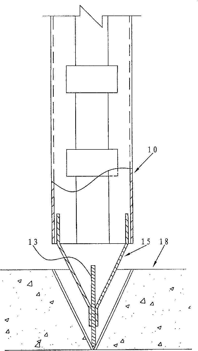
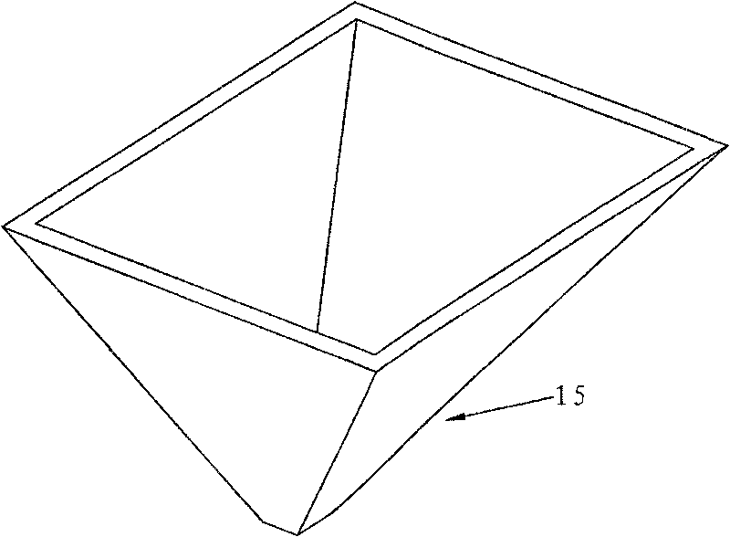
[0034] refer to Figure 4 , the figure shows the lattice column assembly provided by the present invention and its installation state. The lattice column assembly includes a lattice column 30 , a bottom positioner 20 and a top positioner 40 .

[0035] The above-mentioned lattice column 30 is a lattice column used in piles. For example, when constructing a construction site, especially in a basement by reverse construction, first build the peripheral wall 50 of the pile and the pile core concrete 52 at the bottom, and then Then install the lattice column assembly on the pile core concrete in the retaining wall 50 .

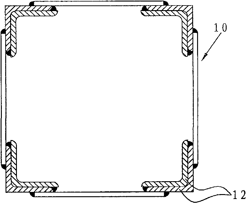
[0036] refer to Figure 5 , the figure shows the cross-sectional shape of the lattice column 30 provided by the present invention. The above-mentioned lattice column 30 is a combined frame surrounded by two or more section steel...


PUM


Abstract

The invention discloses lattice column components used in pile and an installation method. The components comprise a lattice column, a top localizer, and a bottom localizer; the lattice column is a combined column which is formed by connecting profiled bar batten plates; the bottom localizer is in a shape of flat cup, which comprises a cup body, a flat-shaped base which is connected with the cup body, and a guide section which is connected with one side of the cup body away from the base; the lower end of the lattice column is matched with the cup body, and the base is supported by a profiledbar. The bottom localizer is arranged at a condensate concrete core, thereby the position of the bottom localizer can be adjusted conveniently and accurately; the guide section can make the lattice column drop into the matching cup, so which can reduce disturbance and position accurately; the profiled bar is an angle iron which is rolled by thick steel plate, which is less a related joint vacant position than the double-welding angle iron in the same thickness, thereby which has no welding deformation and can ensure the stiffness of the angle iron; the groined top localizer can be independently assembled with sub-components, which can be adjusted flexibly, so that the verticality of the lattice column and the accuracy of the top positioning can be ensured.

Description

technical field [0001] The invention relates to a permanent load-bearing steel structural component for building and its installation method, in particular to a lattice column component placed inside a pile during building construction and its installation method. Background technique [0002] Lattice column refers to a composite column formed by connecting two or more angle steels or channel steels with connecting plates. It has a wide range of uses. For example, in the reverse construction of the basement, this steel structural member can be used for vertical support. [0003] figure 1 , figure 2 , image 3 The installation state of the traditional lattice column 10 and its bottom locator 15 and the perspective view of the traditional bottom locator 15 are shown, Figure 7 is the top locator 16 and the installation diagram. The bottom locator 15 of this lattice column should be installed before the final setting of the pile core concrete 18 for the first pouring, whi...

Claims


Application Information

Patent Timeline
Patent Type & Authority Patents(China)
IPC IPC(8): E04B1/24E21D11/28E04C3/32
Inventor 江永富吴祥威
Owner GUANGZHOU CONSTR ENG
Why Eureka
Try Eureka