Automatic roller clutching disc bonding machine
A welding machine and drum technology, applied in welding equipment, auxiliary welding equipment, welding/cutting auxiliary equipment, etc., can solve the problems of inability to realize automatic production, dependence on product quality and production efficiency, and high labor intensity of workers
Inactive Publication Date: 2008-10-15
河南天隆输送装备有限公司
View PDF0 Cites 6 Cited by
- Summary
- Abstract
- Description
- Claims
- Application Information
AI Technical Summary
Problems solved by technology
Welding machines with this structure are all manually operated for electric welding. Not only is the labor intensity of the workers high, but also the product quality and production efficiency depend on the proficiency and skills of the operator, and automatic production cannot be realized.
Method used
View moreImage
Smart ImageViewing Examples

Examples
Embodiment Construction
Login to View More PUM
 Abstract
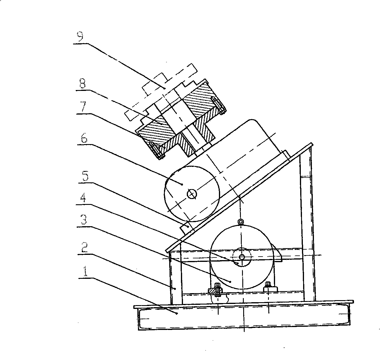
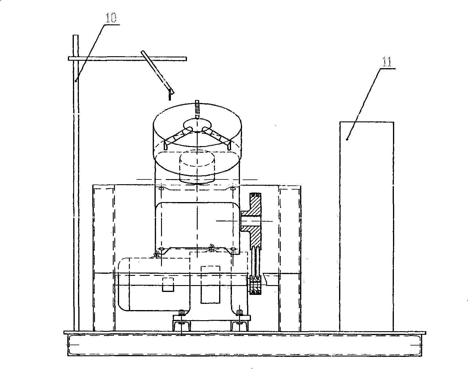
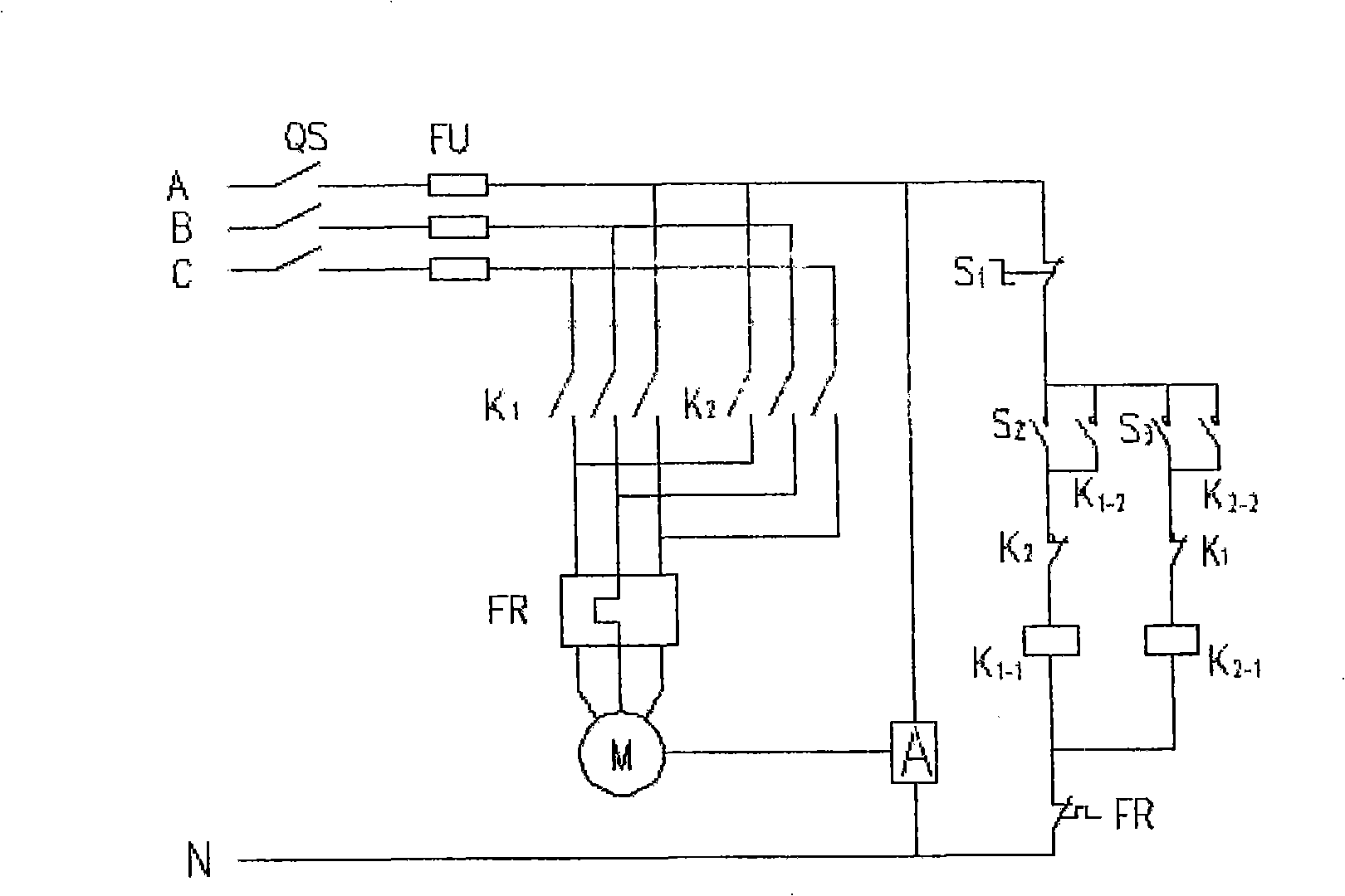
The invention discloses an automated drum flange welder, which comprises a drum flange welder. A motor is arranged on the chassis and the bracket of the welder; a small belt wheel is fixed on the output shaft of the motor; a reducer is fixed on a flange plate; the output shaft of the reducer is fixed on the chuck of a workpiece; a big belt wheel is fixed on the input shaft of the reducer; a transmission belt is connected on the big belt wheel and the small wheel; an electric control cabinet is installed on one side of the chassis; an actiyator and a thermorelay are mounted inside the chassis; leads on the actiyator and the thermorelay are connected with the motor; two contactor switches, a corresponding SBF and an SBR, and a stop button are connected in parallel on the actiyator in the circuit between the actiyator and the thermorelay; and a three-way circuit breaker and the corresponding fuse protector are connected in parallel on the thermorelay. The welder has the advantages of high level of automation, high quality and high efficiency.
Description
Automatic drum welding machine Technical field: The invention relates to welding, in particular to an automatic roller-joint welding machine suitable for processing and forming rollers and trays on conveyors. Background technique: The existing drum plate welding machine includes a chassis and a bracket, a flange is fixed on the upper slope of the bracket, and a three-jaw self-centering work chuck is rotatably connected to the flange. The top is connected with a welding torch connected to the power supply with a support rod from one side of the base. The welding machines of this structure all use manual operation for electric welding. Not only is the labor intensity of the workers high, but also the product quality and production efficiency depend on the proficiency and skills of the operators, and automatic production cannot be realized. Invention content: The object of the present invention is to provide an automatic drum welding machine with high degree of automatic ...
Claims
Login to View More Application Information
Patent Timeline
 Patent Type & Authority Applications(China)
IPC IPC(8): B23K37/047
Inventor 张新民洪胜雁秦守宾扬静云魏风胜
Owner 河南天隆输送装备有限公司
Features
- R&D
- Intellectual Property
- Life Sciences
- Materials
- Tech Scout
- Unparalleled Data Quality
- Higher Quality Content
- 60% Fewer Hallucinations
Learn More Browse by: Latest US Patents, China's latest patents, Technical Efficacy Thesaurus, Application Domain, Technology Topic, Popular Technical Reports.
© 2025 PatSnap. All rights reserved.Legal|Privacy policy|Modern Slavery Act Transparency Statement|Sitemap|About US| Contact US: help@patsnap.com