Torsional moment and force loading unit for shield excavation simulation

A technology of loading device and shield tunneling, which is applied in the direction of measuring device, machine/structural component testing, instrument, etc., to achieve the effect of easy operation

Inactive Publication Date: 2008-10-15
TSINGHUA UNIV
View PDF2 Cites 27 Cited by
  • Summary
  • Abstract
  • Description
  • Claims
  • Application Information

AI Technical Summary

Problems solved by technology

[0005] The purpose of the present invention is to provide a mechanical device for simulating torque and force loading of large-scale shield tunneling on the basis of not buildi

Method used


Image

  • Torsional moment and force loading unit for shield excavation simulation
  • Torsional moment and force loading unit for shield excavation simulation
  • Torsional moment and force loading unit for shield excavation simulation

Examples


Embodiment Construction

[0020] The technical scheme of the present invention will be further described below in conjunction with the accompanying drawings.

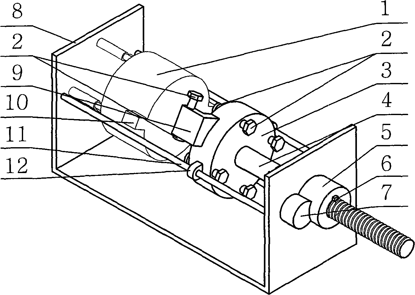
[0021] Such as figure 1 As shown, this embodiment mainly includes a loading disc 3 , a set of force loading unit installed on the loading disc 3 , a set of torque loading unit and a linear motion system. The specific structure is as figure 1 As shown, it includes a frame 8, a loading tray 3, and a simulated shield head 1. The simulated shield head 1 is arranged at the left end of the frame 8 , and the loading disk 3 is arranged at the right end of the frame 8 . A pair of horizontal slide rails 11 are also fixed on the frame 8, and the connectors 12 fixed on both sides of the loading tray are sleeved on the outer surface of the slide rails, so that the loading tray can slide along the slide rails, and the axis of the loading tray 3 is in line with the analog The axis of shield head 1 is on a straight line. A pair of force-bearing protrusions ...


PUM


Abstract

The invention discloses a torque and force loading device for shield tunneling simulation, belonging to the tunnel engineering technical field. The device comprises a frame, a simulation shield head, a loading disc and a slide rail fixed on the frame. The simulation shield head is arranged on the left end of the frame. A force bearing projection is arranged on a cylinder-shaped lateral surface at the right end of the simulation shield head. The loading disc is arranged on the right end of the frame and is slidably connected with the slide rail. The right end of the loading disc is fixedly connected with a lead screw which passes through the frame to be connected with a reduction device and an electric motor in sequence. A loading projection is fixed on the cylinder-shaped lateral surface at the left end of the loading disc. A force loading unit which passes through the loading projection is arranged on the loading projection. When the simulation shield head is contacted with the loading disc, an end surface of the force loading unit is contacted with the force bearing projection on the simulation shield head. Force loading units which pass through the loading disc along the axial direction are uniformly arranged on the loading disc along the circumferential direction. The device realizes tunneling simulation of the shield under different working conditions by adjusting the force loading units on a force loading system and a torque loading system.

Description

technical field [0001] The invention belongs to the technical field of tunnel engineering, in particular to a loading device capable of simulating the torque and force received during the excavation process of a large shield tunneling machine. Background technique [0002] To build a tunnel with the shield method is to use the cutterhead to rotate and cut the soil and the jack to push the shield machine forward. Therefore, the cutterhead and propulsion system are the key components in the shield machine. The calculation and analysis of the cutterhead torque and the jack thrust , is the premise to ensure the smooth cutting and advancing of the shield. [0003] The shield machine is an unconventional large-scale construction machine with many and complex problems. It is not enough to rely solely on theoretical analysis and calculation, and it depends on experimental research. On the other hand, due to its high cost, it is not easy to build a real object for testing. It is a b...

Claims


Application Information

Patent Timeline
IPC IPC(8): E21D9/06G01M99/00
Inventor 唐晓强王立平邓孔书冯平法
Owner TSINGHUA UNIV
Why Eureka
Try Eureka