Thin film residual stress component analytical equipment
A residual stress and analysis device technology, applied in the direction of measurement device, analysis material, material thermal analysis, etc., can solve the problem of firmness threat, and achieve the effect of improving the plating process, convenient operation and rapid measurement
Inactive Publication Date: 2010-11-10
ZHEJIANG UNIV
View PDF0 Cites 0 Cited by
- Summary
- Abstract
- Description
- Claims
- Application Information
AI Technical Summary
Problems solved by technology
But almost all films have huge stress, which poses a great threat to the performance of the film, especially the firmness
Method used
View moreImage
Smart ImageViewing Examples
Examples
Embodiment Construction
Login to View More PUM
 Abstract
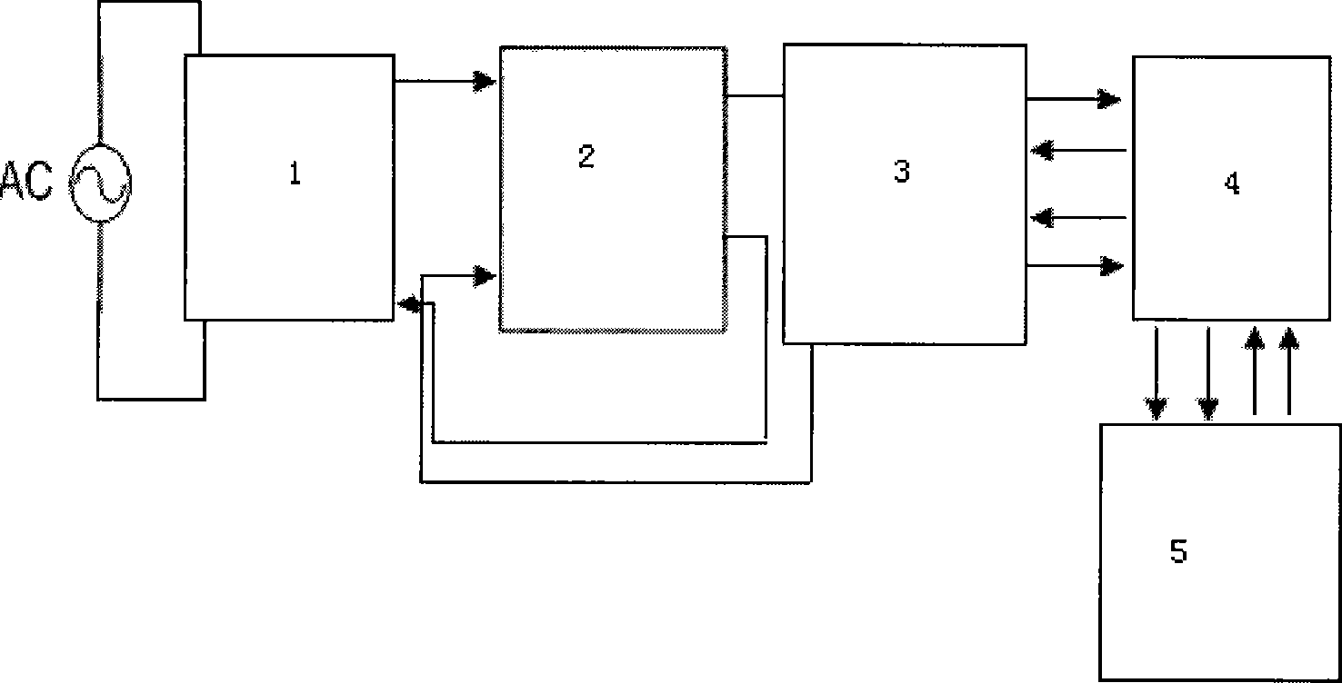
The invention discloses a device for analyzing compositions of residual stress of a film. The invention comprises a relay temperature control instrument, a heating plate driving circuit, a substrate fixture, an interferometer and a computer, wherein, the relay temperature control instrument is connected with the heating plate driving circuit, the substrate fixture, the interferometer and the computer in turn; the substrate fixture comprises a first copper sheet, a second copper sheet, an aluminum sheet, iron clamping pieces, a sample fixation circular orifice, a thermal resistance and MCH heating plates; the thermal resistance and two MCH heating pieces are fixed on the back of the first copper sheet; fixed grooves are arranged on both sides of the first copper sheet; the second copper sheet is inserted into the fixed grooves which are arranged on both sides of the first copper sheet; two iron clamping pieces are fixed on both sides of the upper end of the second copper sheet; the aluminum sheet is clamped on the two iron clamping pieces; and the sample fixation circular orifice is arranged on the aluminum sheet. The invention is a non-destructive detection method and has the advantages of convenient operation, quick measurement, high precision, capability of simultaneously determining a plurality of parameters and performing stress component analysis and so on.
Description
An analysis device for residual stress components of thin films technical field The invention relates to a device for analyzing residual stress components of thin films. Background technique Optical thin films are widely used. Beam splitters, cut-off filters and bandpass filters used in optical systems are realized by optical thin films; in addition, a large number of thin-film devices are also used in optical fiber communications and laser optics; thin-film It is also widely used in information storage, semiconductor devices, photoelectric display and other fields. But almost all films have huge stress, which poses a great threat to the performance of the film, especially the firmness. Therefore, it is of great significance to study the stress in the thin film. In terms of composition, the stress in the film is mainly composed of intrinsic stress (also called internal stress), external stress and thermal stress. Intrinsic stress is related to the chemical composition, ...
Claims
Login to View More Application Information
Patent Timeline
 Patent Type & Authority Patents(China)
IPC IPC(8): G01N21/45G01N25/00
Inventor 章岳光陈为兰沈伟东王颖顾培夫黄文彪
Owner ZHEJIANG UNIV
Features
- R&D
- Intellectual Property
- Life Sciences
- Materials
- Tech Scout
- Unparalleled Data Quality
- Higher Quality Content
- 60% Fewer Hallucinations
Learn More Browse by: Latest US Patents, China's latest patents, Technical Efficacy Thesaurus, Application Domain, Technology Topic, Popular Technical Reports.
© 2025 PatSnap. All rights reserved.Legal|Privacy policy|Modern Slavery Act Transparency Statement|Sitemap|About US| Contact US: help@patsnap.com


