
Radio frequency power source system and plasma reactor chamber using the radio frequency power source system

A radio frequency power source and radio frequency power technology, applied in the field of radio frequency power source, can solve the problems of large footprint and high price of equipment

Active Publication Date: 2008-10-15
ADVANCED MICRO FAB EQUIP INC CHINA
View PDF4 Cites 15 Cited by
  • Summary
  • Abstract
  • Description
  • Claims
  • Application Information

AI Technical Summary

Problems solved by technology

But this design is expensive and the equipment occupies a large area

Method used


Image

  • Radio frequency power source system and plasma reactor chamber using the radio frequency power source system
  • Radio frequency power source system and plasma reactor chamber using the radio frequency power source system
  • Radio frequency power source system and plasma reactor chamber using the radio frequency power source system

Examples


Embodiment Construction

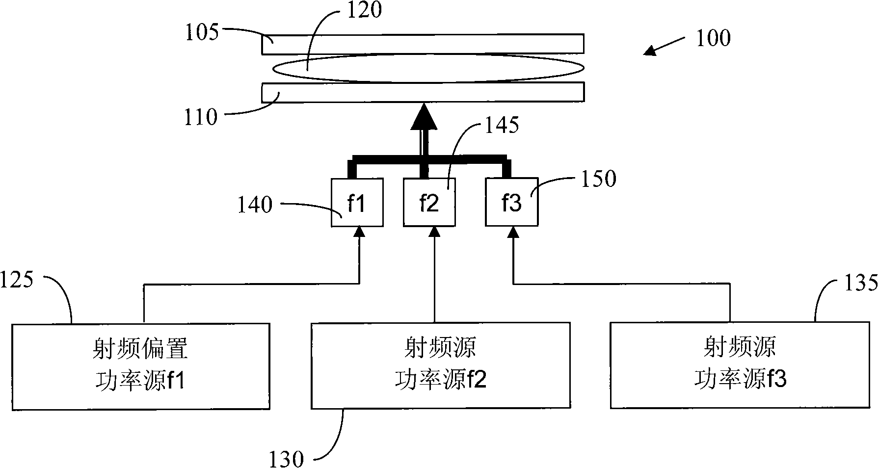
[0025] figure 1 It is a schematic diagram of a multi-frequency plasma reaction chamber in the prior art, which is connected with a radio frequency bias power source or a radio frequency bias power generator (one RF bias power generator) and two source radio frequency power sources or source radio frequency power Generators (two source RF power generators). in particular, figure 1 The plasma reaction chamber 100 is shown having an upper electrode 105, a lower electrode 110 and a plasma 120 generated between the two electrodes. Usually, the upper electrode 105 is generally embedded on the top cover of the reaction chamber, and the lower electrode 110 is generally embedded on the lower cathode assembly, which is used to place semiconductor process pieces to be processed, such as semiconductor wafers. Such as figure 1 As shown in , the bias RF power source 125 provides RF power to the reaction chamber 100 through the matching circuit 140 . A radio frequency bias frequency f1, ...


PUM


Abstract

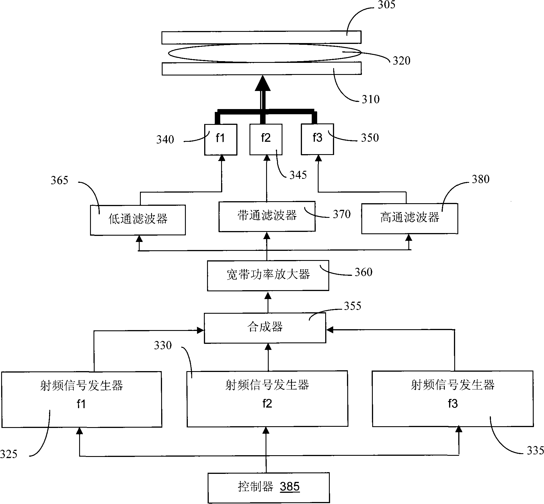
The invention relates to a radio frequency power source which is applied to a plasma reaction chamber. A frequency synthesis method or a radio frequency signal oscillator is adopted to generate N radio frequency signals and a wideband power amplifier is used for amplifying the N radio frequency signals, and then the amplified radio frequency signals are separated. Therefore, the radio frequency power with various frequencies is outputted by a radio frequency system. Electively, the frequencies can be switched, thereby users can select from the frequencies outputted by the radio frequency power source system. The invention further discloses a plasma reaction chamber which uses the radio frequency power source.

Description

【Technical field】 [0001] The invention relates to a radio frequency power source applied in a plasma reaction chamber, in particular to a radio frequency power source system capable of generating multiple frequencies and a plasma reaction chamber using the radio frequency power source system. 【Background technique】 [0002] Plasma reaction chambers using two radio frequency frequencies (dual frequency) already exist in the prior art. Generally, the frequency of the RF bias power (RF bias power) received by the dual-frequency plasma reaction chamber is lower than about 15 MHz, and the frequency of the RF source power (RF source power) is higher, generally 40-200 MHz. The RF bias power refers to the RF power used to control ion energy and energy distribution, and the RF source power refers to the RF power used to control ion dissociation or plasma density in the plasma. In certain applications, etch processes are performed in plasma chambers using a bias frequency of 2MHz or ...

Claims


Application Information

Patent Timeline
Patent Type & Authority Applications(China)
IPC IPC(8): H05H1/46H05H1/30
CPCH01J37/32165H01J37/32082H01J37/32174H03H7/46H03H11/34
Inventor CHEN JINYUANYIN ZHIYAOQIAN XUEYUNI TUQIANGFAN ZHONGHAO
Owner ADVANCED MICRO FAB EQUIP INC CHINA
Learn More