Amplification stage and wideband power amplifier

a technology of amplifier and power amplifier, which is applied in the direction of amplifier with semiconductor devices/discharge tubes, amplifier combinations, amplifier modifications to extend bandwidth, etc., can solve the problems of low stability and/or power supply voltage drops at the output terminal of the device, and the narrow frequency operational bandwidth of the recent traditional high-power doherty power amplifier,

Active Publication Date: 2015-10-15
NXP USA INC
View PDF2 Cites 14 Cited by
  • Summary
  • Abstract
  • Description
  • Claims
  • Application Information

AI Technical Summary

Problems solved by technology

One of the most notorious limitation of recent traditional high power Doherty power amplifiers was a narrow frequency operational bandwidth, which was not properly analyzed and frequently mentioned and reported in papers as presumably caused by the impedance inverter or so called Doherty Combiner.
Another issue for power amplifiers is low stability and / or drops of the power supply voltage at the output terminal of the device, which happen during and after at sharp raises and peaks of the amplified signal envelope.
This can be caused by parasitic inductances existing between the active die and the power supply terminal.
This creates an undesired parasitic inductance Ld by wires connecting the drain metal bar of the die to the output lead of the package and / or the Doherty power combine network.
This results in an even larger phase shift which limits the operational bandwidth well below that of the 30% claimed by U.S. Pat. No. 7,078,976.
This parasitic inductance is especially harmful in case large dies are used, which even further limits the realization of a wideband high power Doherty power amplifier.
As a result, the phase characteristics of the input network of the traditional Doherty power amplifier has a different rate versus frequency than that the output network, which even further affects operational bandwidth.

Method used


Image

  • Amplification stage and wideband power amplifier
  • Amplification stage and wideband power amplifier
  • Amplification stage and wideband power amplifier

Examples


Embodiment Construction

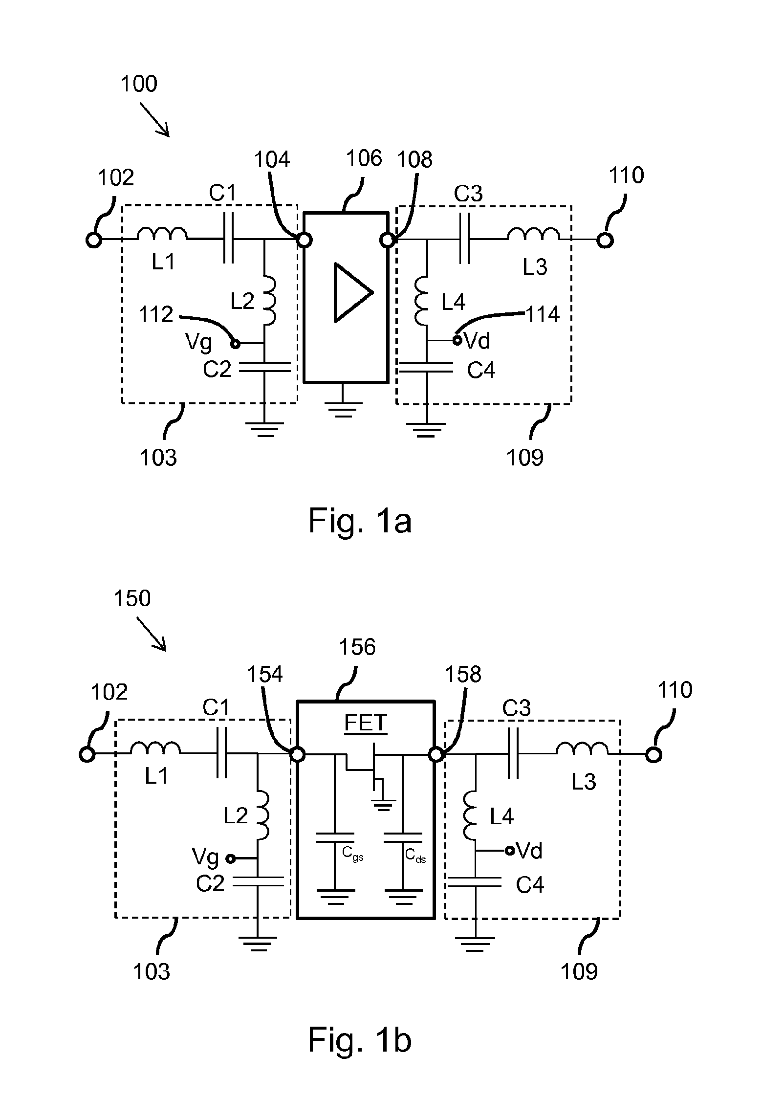
[0028]FIG. 1a schematically shows in a circuit diagram an example of an embodiment of an amplification stage 100. The amplification stage 100 is configured to be used in a power amplifier and is configured to amplify a signal in a bandwidth around an operational frequency. The amplification stage 100 comprises a stage input terminal 102, a stage output terminal 110, an amplifier 106, an input compensation network 103 and an output compensation network 109. The stage input terminal 102 receives a signal which must be amplified by the amplification stage 100. The stage output terminal 110 provides an amplified signal. The amplifier 106 comprises an amplifier input terminal 104 and an amplifier output terminal 108. The amplifier 106 is configured to amplify a signal received at the amplifier input terminal 104 towards a signal at the amplifier output terminal 108. The input compensation network 103 is coupled in between the stage input terminal 102 and the amplifier input terminal 104....


PUM


Abstract

An amplification stage and a wideband power amplifier are provided. The amplification stage includes a stage input terminal, a stage output terminal, an amplifier, an input compensation network, and in output compensation network. At the stage input terminal is received a signal which is provided via the input compensation network to the amplifier. The input compensation network filters the signal to allow a wideband operation of the amplification stage around an operational frequency. The amplified signal provided by the amplifier is provided via the output compensation network to the stage output terminal. The output compensation network configured to allow a wideband operation of the amplification stage around the operational frequency with a minimal phase shift and distortion of amplitude and phase frequency response. The wideband power amplifier includes a plurality of amplification stage combined with transmission lines or their lumped element equivalents in a specific circuit topology.

Description

FIELD OF THE INVENTION[0001]This invention relates to amplification stages for use in wideband power amplifiers and relates to wideband power amplifiers. In specific embodiments, the wideband power amplifier may be a Doherty amplifier.BACKGROUND OF THE INVENTION[0002]The mobile communications industry is ever demanding for more efficient power amplifiers for mobile base stations, which are also able to operate in a wider frequency band allowing a larger data rate or traffic (i.e. transmit more information per second). For example, one carrier of an older generation mobile WCDMA occupies 4 MHz of bandwidth, while new generations like LTE use 10 MHz and 20 MHz carrier bandwidth. In proposals for future generations of mobile communication technology, the carrier bandwidth is going for 40 MHz up to 100 MHz of digital modulation band per carrier.[0003]Power amplifiers operating as final stages of mobile base station transmitters are the most demanding components due to required output po...

Claims


Application Information

Patent Timeline
Patent Type & Authority Applications(United States)
IPC IPC(8): H03F1/42H03F3/60H03F1/02H03F3/21H03F3/195H03F3/24
CPCH03F1/42H03F3/195H03F3/245H03F2203/21142H03F3/211H03F3/604H03F2203/21106H03F1/0288H03F3/24H03F3/602
Inventor BLEDNOV, IGOR
Owner NXP USA INC
Why Eureka
Try Eureka