Double L-shaped cubic modularized self-reconstruction robot based on rotary hook hole

A rotary hook and cube technology, applied in the field of robotics, can solve the problems of insufficient flexibility of motion of array robots, inability to move efficiently, and limit self-reconfiguration, and achieve simplified inspection and maintenance processes, suitable for batch manufacturing, and energy saving. Effect

Active Publication Date: 2008-10-22
HARBIN INST OF TECH
View PDF0 Cites 27 Cited by
  • Summary
  • Abstract
  • Description
  • Claims
  • Application Information

AI Technical Summary

Problems solved by technology

[0011] The purpose of the present invention is to solve the lack of flexibility of the existing array robot movement, and the robot cannot move efficiently after forming the robot; most of the connecting mechanisms of the existing array robot modules adopt pin-hole type, electromagnetic type or permanent magnet type structure, but the separation operation requires additional separation space, limiting the ability of self-reconfiguration
The electromagnetic connection mechanism has problems such as large volume, heavy weight, and high heat generation.

Method used


Image

  • Double L-shaped cubic modularized self-reconstruction robot based on rotary hook hole
  • Double L-shaped cubic modularized self-reconstruction robot based on rotary hook hole
  • Double L-shaped cubic modularized self-reconstruction robot based on rotary hook hole

Examples


specific Embodiment approach 1

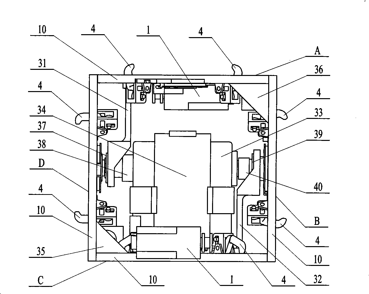
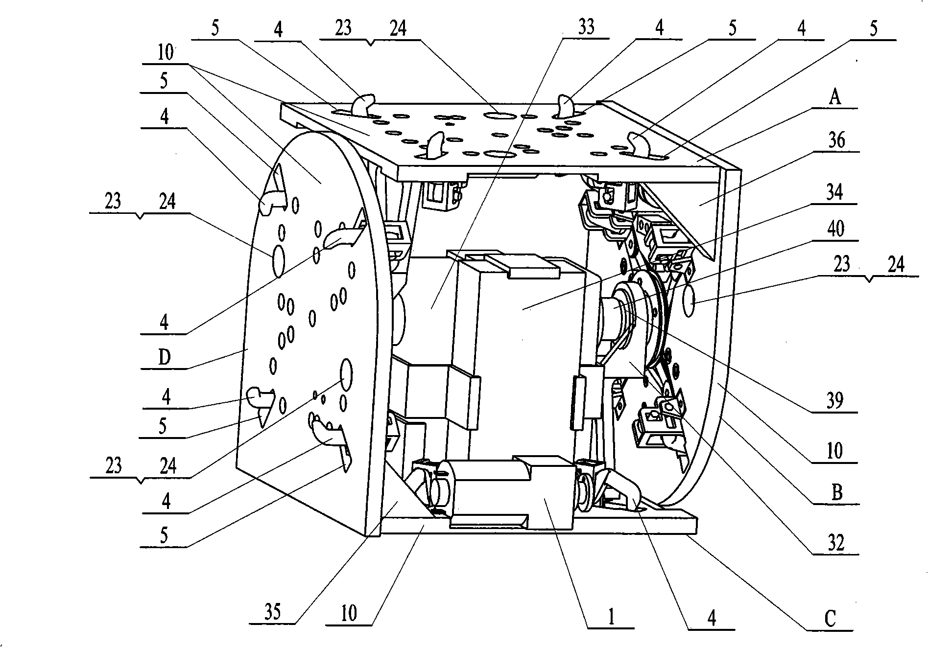
[0014] Specific implementation mode one: (see figure 1 ~ Figure 7) This embodiment consists of an active module and a passive module. The active module consists of a first active connection module A, a second active connection module B, a third active connection module C, a fourth active connection module D, and a first support frame 31. The second support frame 32, the first servo steering gear 33, the first battery 34, the first bearing 37, the support shaft 38 of the first servo steering gear, the second bearing 39 and the torque output shaft of the first servo steering gear 40, one end of the first active connection module A is fixedly connected to one end of the second active connection module B, one end of the third active connection module C is fixedly connected to one end of the fourth active connection module D, and one end of the first support frame 31 It is fixedly connected with the inner side of the first active connection module A, one end of the second support f...

specific Embodiment approach 2

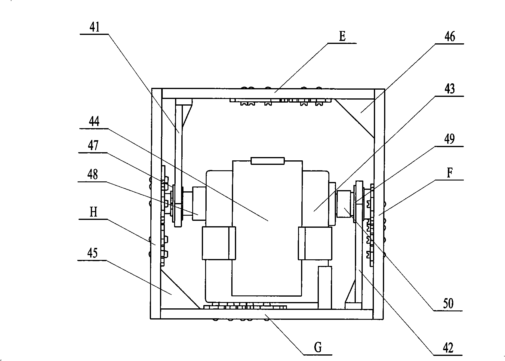
[0015] Specific implementation mode two: (see figure 2 , Figure 4 and Fig. 5) the difference between this embodiment and specific embodiment one is that it has increased four passive connection module permanent magnets 17 and two active connection module permanent magnets 24, the first passive connection module E, the second passive connection module F, the third passive connection module G and the fourth passive connection module H are provided with four tapered holes 14 orthogonally distributed, and a passive connection module permanent magnet 17 is fixed in each tapered hole 14, and each panel 10 There are two tapered holes 23 on the top, and an active connection module permanent magnet 24 is fixed in each tapered hole 23. The two active connection module permanent magnets 24 on each panel 10 are respectively connected to the first passive connection module E, the second passive connection module The two passive connection module permanent magnets 17 on the opposite corn...

specific Embodiment approach 3

[0016] Specific implementation mode three: (see figure 1 ) The difference between this embodiment and the second embodiment is that it adds a first rib 35 and a second rib 36, and the second rib 36 is fixed at the intersection of the first active connection module A and the second active connection module B On the inner wall at , the first rib 35 is fixed on the inner wall at the corner of the third active connection module C and the fourth active connection module D. Others are the same as in the second embodiment. The added first ribs 35 and second ribs 36 play a supporting role on the first active connection module A and the second active connection module B as well as the third active connection module C and the fourth active connection module D.


PUM


Abstract

The invention provides a double L-shaped cubic modularized self-reconstructing robot based on rotational hook hole connection, which relates to a robot. The present invention aims at solving the problems that the existing array-typed robot is not flexible enough in motion and the robot after being assembled can not efficiently move, as well as the problems of large volume, heavy weight and large heat productivity, and the like, in an electromagnetic connecting mechanism. The present invention is characterized in that a first drive connecting module is fixedly connected with a second drive connecting module; a third drive connecting module is fixedly connected with a fourth drive connecting module; a first driven connecting module is fixedly connected with a second driven connecting module; a third driven connecting module is fixedly connected with a fourth driven connecting module. The present invention has the self-reconstructing function of local modules of the array-typed system and the motional function of integrated configuration of a tandem-typed system. The load/deadweight rate of the module is 4.5:1 and the drive module or the driven module can be exchanged automatically. The mechanism does not need to maintain the energy in the connecting state and the disconnecting state, thus saving the energy.

Description

technical field [0001] The present invention relates to a robot. Background technique [0002] Modular self-reconfigurable robot, also known as self-metamorphic robot, is a new discipline emerging in the field of robotics research in the past ten years, and it is a hot and difficult point in current robotics research. It refers to the use of the connectivity and interchangeability between robot modules, as well as the surrounding environment information sensed by the module sensors, through the interoperation between a large number of modules to change the overall configuration, expand the movement form, realize different movement gaits, complete Corresponding movement and manipulation tasks. It has the following characteristics: 1. Self-reconfiguration function: The robot can select the corresponding configuration through artificial intelligence computing technology according to the change of the environment and tasks, and the autonomous control module is reorganized to th...

Claims


Application Information

Patent Timeline
Patent Type & Authority Applications(China)
IPC IPC(8): B25J3/00B25J19/00
Inventor 赵杰朱延河唐术锋樊继北任宗伟
Owner HARBIN INST OF TECH
Why Eureka
Try Eureka