Railway bearing intelligent on-line detection method and its device

A railway bearing and detection method technology, which is applied in mechanical bearing testing, railway vehicle testing, etc., can solve problems such as large randomness, low reliability, and influence of faulty bearing detection and judgment, and achieve the effect of reducing labor intensity

Inactive Publication Date: 2008-10-22
洛阳铭昊测控科技有限公司
0 Cites 45 Cited by

AI-Extracted Technical Summary

Problems solved by technology

[0003] Although the country has invested a large amount of funds in the purchase of vehicles, due to the high-speed and heavy load of domestic railway passenger and freight vehicles, the passenger and freight vehicles are overloaded.
However, the abnormal information, structural health, and fault diagnosis of the wheel set bearings under the operating state of the railway vehicle are completely manually detected (station repair or section repair), and the workers manually judge the state based on their feelings, and the reliability is not high. In addition, in the station repair There is also a method of using special equipment to simulate loading and high-speed rotation of rolling bearings in passenger and freigh...

Method used

In the detection device of the present invention, the height of the fuselage table top is adapted to the installation height of the railway wheel set bearing (taking 200~300mm), and the bottom surface of the fuselage is provided with a structure etc. connected with the trailer; in the main shaft system, the main shaft 6 Installed in the main shaft box 8 and driven by the transmission pulley 28, according to the working speed of the railway wheel set bearing, the main shaft speed range is determined to be 520-1080r/min. The motion transmission pair is driven by a belt whose vibration frequency is far from that of the bearing, and the rotation of the output spindle is supported by a hydrostatic bearing 7, which can ensure the stable operation of th...

Abstract

The invention belongs to a technology for detecting wheel set bearings of running positions of a railway carriage and a lorry, providing an intelligent online detecting method for a railway bearing and a device using the same. The device mainly comprises a lathe bed (1), a vibration detecting mechanism, a torque detecting mechanism, a correcting mechanism and a computer (38). The method and the device have the advantages that: the intelligent online detecting method for the railway bearing and the device using the same can be used for detecting abnormal information, structural health and failure diagnosis of wheel set bearings for internal railway lorries in utilization states. The method can replace the prior detecting method which completely adopts manual detection to detect the condition of the wheel set bearing in non-disassembly condition by the manual operation of a worker according to feeling in the rolling stock depot. Compared with over 600,000 railway carriages and lorries in the country, the method and the device not only reduce labor intensity for workers, but also have a positive promoting effect for preventing accidents, so that bearing online detection and analysis for railway in the country can be quickly and healthily developed.

Application Domain

Technology Topic

Image

  • Railway bearing intelligent on-line detection method and its device
  • Railway bearing intelligent on-line detection method and its device
  • Railway bearing intelligent on-line detection method and its device

Examples

  • Experimental program(1)

Example Embodiment

[0028] The present invention can be explained in more detail with reference to the following examples; however, it should be noted that the present invention is not limited to the following examples.
[0029] The intelligent online detection method and device for railway bearings of the present invention are described in conjunction with the accompanying drawings. The method and device of the present invention are also applicable to the online detection and analysis of wheel set bearings of various locomotives.
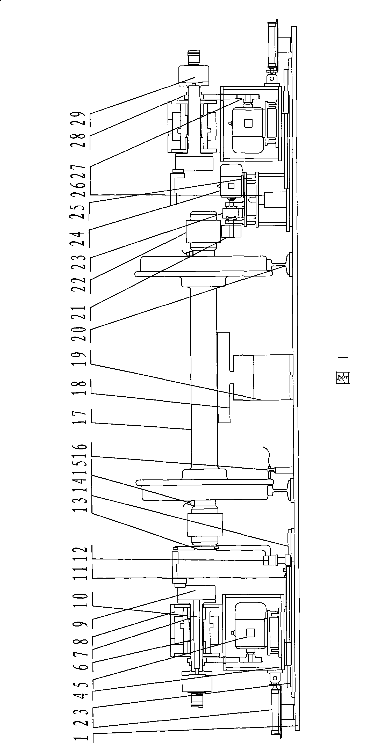
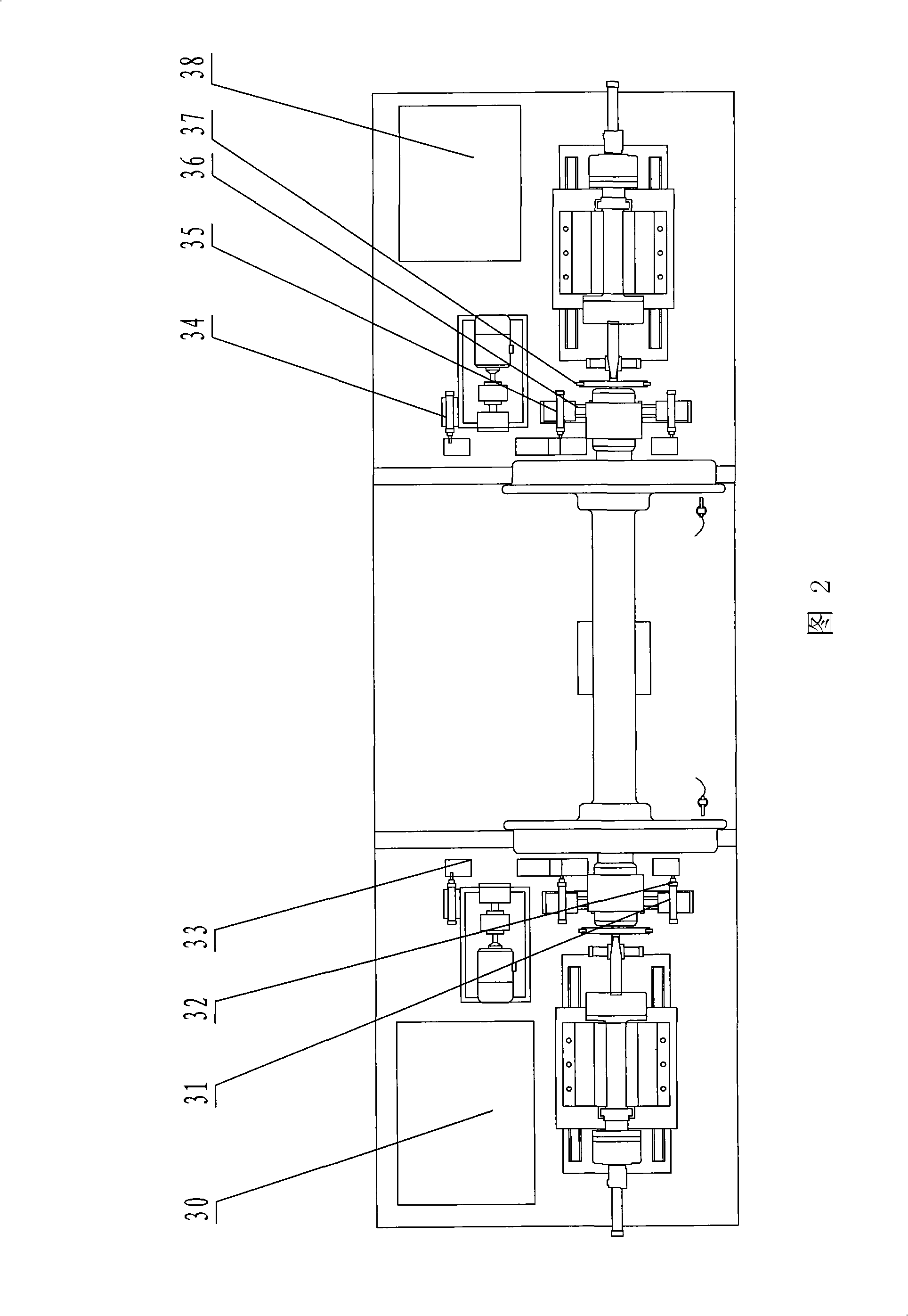
[0030]Referring to Fig. 1 and Fig. 2, first roll the wheel set 17 to be detected into the detection area, and after reaching the detection area and contacting the proximity switch 16, the proximity switch 16 sends a voltage signal to the computer 38, and the computer 38 outputs instructions to the pneumatic Solenoid valve, stops cylinder 35 actions, and the stopper 33 of its piston front end stops wheel pair 17, stops cylinder 32 actions, and its piston front end stopper 33 stretches out forward, and wheel pair 17 is clipped between two stoppers 33; The first cylinder 31 moves and drives the blocking cylinder 32 on it to advance to the wheel pair 17, so that the wheel pair 17 is located between the two sets of vibration detection mechanisms, and the rough positioning of the wheel pair 17 is completed; after completion, the magnetic control switch sends a voltage signal to the computer 38. The computer 38 outputs instructions to the hydraulic solenoid valve, and the supporting oil cylinder 19 moves upwards. The V-shaped block 18 installed on the supporting oil cylinder 19 jacks up the wheel set 17 axles. 22 and the main shaft of the vibration detection mechanism are located on the same vertical plane. After completion, the proximity switch 16 sends a voltage signal to the computer 38, and the computer 38 outputs a pneumatic solenoid valve. The swing cylinder 12 of the calibration mechanism moves to swing the calibration ring 13 to a position concentric with the main shaft , the magnetic control switch sends a voltage signal to the computer 38, the computer 38 outputs the pneumatic solenoid valve, the thrust cylinder 11 of the calibration mechanism acts, and the thrust cylinder 11 makes the swing cylinder and the calibration ring 13 advance to the wheel pair 17 along the small linear guide bearing 14, Put the calibration ring 13 on the wheel set bearing 22, four optical fiber sensors 37 detect the concentricity between the tested bearing and the calibration ring, and the computer sends an adjustment signal to control the support cylinder 19 to move up and down to make the wheel set bearing 22 align with the calibration ring. The ring 13 is concentric with the main shaft; the computer outputs instructions to make the loading cylinder 2 act, and push the power box 4 and the main shaft system along the linear guide bearing 3 to the wheel set axially, and push it to the chuck 9 to grasp half the size of the wheel set bearing 22 , the proximity switch 16 sends a voltage signal to the computer 38, the computer 38 outputs the hydraulic solenoid valve, the rotary oil cylinder 29 moves, pulls the connecting rod 10 and the small shaft of the chuck, and makes the three claws on the chuck grasp the outer ring of the bearing under test , the inductive sensor sends a voltage signal to the computer 38, and the motor drives the main shaft to run; the vibration sensor 15 collects the vibration signal to the computer 38, and also makes the loading cylinder move outward relative to the wheel pair to axially load the bearing under test and obtain the pressure from the pressure sensor The signal is radially loaded on the bearing under test by the upward movement of the support oil cylinder and the pressure signal is obtained by the pressure sensor; the pressure signal is input to the computer, and the computer 38 analyzes and processes the vibration signal and the pressure signal. If it is qualified, the computer 38 outputs instructions to the pneumatic electromagnetic commutation Valve, sliding table cylinder 31 moves, and the wheel pair 17 is pushed away from the detection area by the blocking cylinder 32; Push it to the torque measurement position, the proximity switch sends a voltage signal to the computer 38, and the computer 38 outputs the pneumatic solenoid valve to block the action of the cylinder 34 and stop the wheel pair by the block 33. Computer signal and instruction block cylinder 35 actions, and wheel pair 17 is clipped between two stoppers 33; The top of the friction wheel 21 of the torque detection mechanism; the magnetic control switch sends a voltage signal to the computer 38, and the computer 38 outputs an instruction pneumatic solenoid valve to lift up the cylinder 26 to make the friction wheel 21 withstand the wheel pair bearing 22 upwards, and the micro motor 24 Drive the friction wheel to drive the wheel set bearing 22 outer rings to rotate; then the torque signal is analyzed and processed by the computer 38 to judge whether it is qualified or not.
[0031] As shown in Figures 1 and 2, the railway bearing intelligent online detection device proposed by the present invention mainly includes a bed 1, a vibration detection mechanism, a torque detection mechanism, a calibration mechanism and a computer 38; the bed 1 located under the stratum is a box structure , the box is filled with river sand; combined with Figure 4 , Figure 5, the vibration detection mechanism is located on the slide plate of the linear guide bearing on the upper part of the bed 1, which is mainly composed of the main shaft system, the chuck 9, the vibration sensor 15, the loading cylinder 2, and the rotary oil cylinder 29, and the power box 4 in the main shaft system is located on the On the slide plate of the linear guide bearing, the main shaft 6 connected to the motor 5 through the transmission belt has a central cavity and is interference fit. The connecting rod 10 passes through the central cavity of the main shaft, one end is connected to the chuck 9, and the other end is connected to the rotary oil cylinder 29. The loading cylinder 2, which is used to push the spindle system to move and can axially load the tested bearing, is located on the bed and outside the spindle system. The piston of the loading cylinder 2 is connected to the power box of the spindle system; the vibration sensor 15 is located on the wheel set under test. On the axle between the bearing and the hub. combine image 3 , the torque detection mechanism is located on the bed, and it is mainly composed of a torque sensor 23, a micro motor 24, a friction wheel 21 and a frame. The jacking cylinder 26 of the outer ring of the bearing under test. combine Image 6 , the calibration mechanism mainly includes a swing cylinder 12, a thrust cylinder 11, a calibration ring 13, and an optical fiber sensor 37; wherein the swing cylinder 12 is located on the slide plate of the small linear guide bearing 14, and the calibration ring 13 is connected with the swing cylinder 12 through a connecting rod and can swing Under the action of the cylinder, the thrust cylinder 11 is located on the bed 1 and connected to the slide plate of the small linear guide bearing, and a plurality of optical fiber sensors 37 are located on the calibration ring 13 and are evenly distributed along the circumference. There is a supporting oil cylinder 19 for jacking up the wheel pair, positioning the axle of the wheel pair and the bearing under test relative to the main shaft of the vibration detection mechanism, and can radially load the bearing under test. The upper end of the piston of the supporting oil cylinder 19 is connected with a V-shaped block 18 and a pressure sensor is set between the piston and the V-shaped block 18. Blocking cylinders 32, 34, 35 are provided to limit the front and rear of the wheel pair and push the wheel pair to move to the desired position, wherein the blocking cylinders 32, 35 are located on the slide table cylinders 31, 36.
[0032] The vibration detection mechanism, the torque detection mechanism and the calibration mechanism are two sets and arranged symmetrically on the left and right, and detect the two bearings of the wheel set at the same time.
[0033] In the detection device of the present invention, the height of the fuselage table is adapted to the installation height of the railway wheel set bearing (taking 200-300 mm), and the bottom surface of the fuselage is provided with a structure connected with the trailer; in the main shaft system, the main shaft 6 is installed on the main shaft In the case 8 and driven by the transmission pulley 28, according to the operating speed of the railway wheel set bearing, the main shaft speed range is determined to be 520~1080r/min. The motion transmission pair is driven by a belt whose vibration frequency is far from that of the bearing, and the rotation of the output spindle is supported by a hydrostatic bearing 7, which can ensure the stable operation of the spindle system and greatly reduce the basic vibration of the testing equipment. The detection method that the outer ring of the railway wheel set bearing rotates but the inner ring does not rotate reduces the interference signal of non-bearing movement. Since the railway wheel set bearings work under the combined radial and axial loads, the rolling elements are not evenly loaded when there is a radial load, and the rolling elements are evenly loaded when the pure axial load is added, which is conducive to identification and timely discovery Anomalies in its work information. The device of the invention is provided with an adjustable axial loading mechanism, and the load value is adjustable within the range of 1-30KN (set by a pressure sensor).
[0034] It should be noted that the program, specific operations, and instructions of the computer system described in the present invention are set as another protection subject, so no further description is given here, but the computer collecting signals involved in the above steps, sending The instruction part is also within the protection scope of the present invention.
[0035] The embodiments chosen herein for the purpose of disclosing the invention are presently considered suitable, but it should be understood that the invention is intended to include all changes and modifications of the embodiments which fall within the concept and scope of the invention.

PUM

no PUM

Description & Claims & Application Information

We can also present the details of the Description, Claims and Application information to help users get a comprehensive understanding of the technical details of the patent, such as background art, summary of invention, brief description of drawings, description of embodiments, and other original content. On the other hand, users can also determine the specific scope of protection of the technology through the list of claims; as well as understand the changes in the life cycle of the technology with the presentation of the patent timeline. Login to view more.

Similar technology patents

Coil discharging device and method of coiling equipment

ActiveCN106553920AHigh degree of autonomyReduce labor intensityWebs handlingEngineeringDischarge procedure
Owner:GUANGDONG JINMING MACHINERY

Classification and recommendation of technical efficacy words

Why Eureka
Try Eureka