Method for driving LCD device

A liquid crystal display device, mode-driven technology, applied in static indicators, nonlinear optics, instruments, etc., can solve the problems of full-screen gradient brightness error, data signal voltage drift, and lower picture quality, so as to reduce power consumption and durability The effect of reducing the pressure range and improving the picture quality

Active Publication Date: 2010-07-28
AU OPTRONICS CORP
View PDF1 Cites 0 Cited by
  • Summary
  • Abstract
  • Description
  • Claims
  • Application Information

AI Technical Summary

Problems solved by technology

[0008] However, in the above-mentioned known liquid crystal display driving method, when displaying a frame, the frame time is only divided into two periods, and data signals of different polarities are sequentially transmitted to odd-numbered lines and even-numbered lines respectively, so the leakage current of the data switch will be As a result, the data signals of adjacent rows have a significant voltage drift difference, thus causing the image moiré effect (Mura effect) to reduce the image quality
In addition, when displaying a picture, the voltage level of the common voltage is only switched once, so the pixel brightness error caused by the voltage level shift of the common voltage is also serious
Furthermore, when the enable order of the gate signals in the first period and the second period are both ascending or descending, it is easy to cause the gradient brightness error of the whole screen, which will also reduce the picture quality.

Method used


Image

  • Method for driving LCD device
  • Method for driving LCD device
  • Method for driving LCD device

Examples


Embodiment Construction

[0059] In order to make the present invention clearer and easier to understand, the method for driving a liquid crystal display device according to the present invention will be described in detail below with specific embodiments in conjunction with the accompanying drawings, but the provided embodiments are not intended to limit the scope of the present invention. .

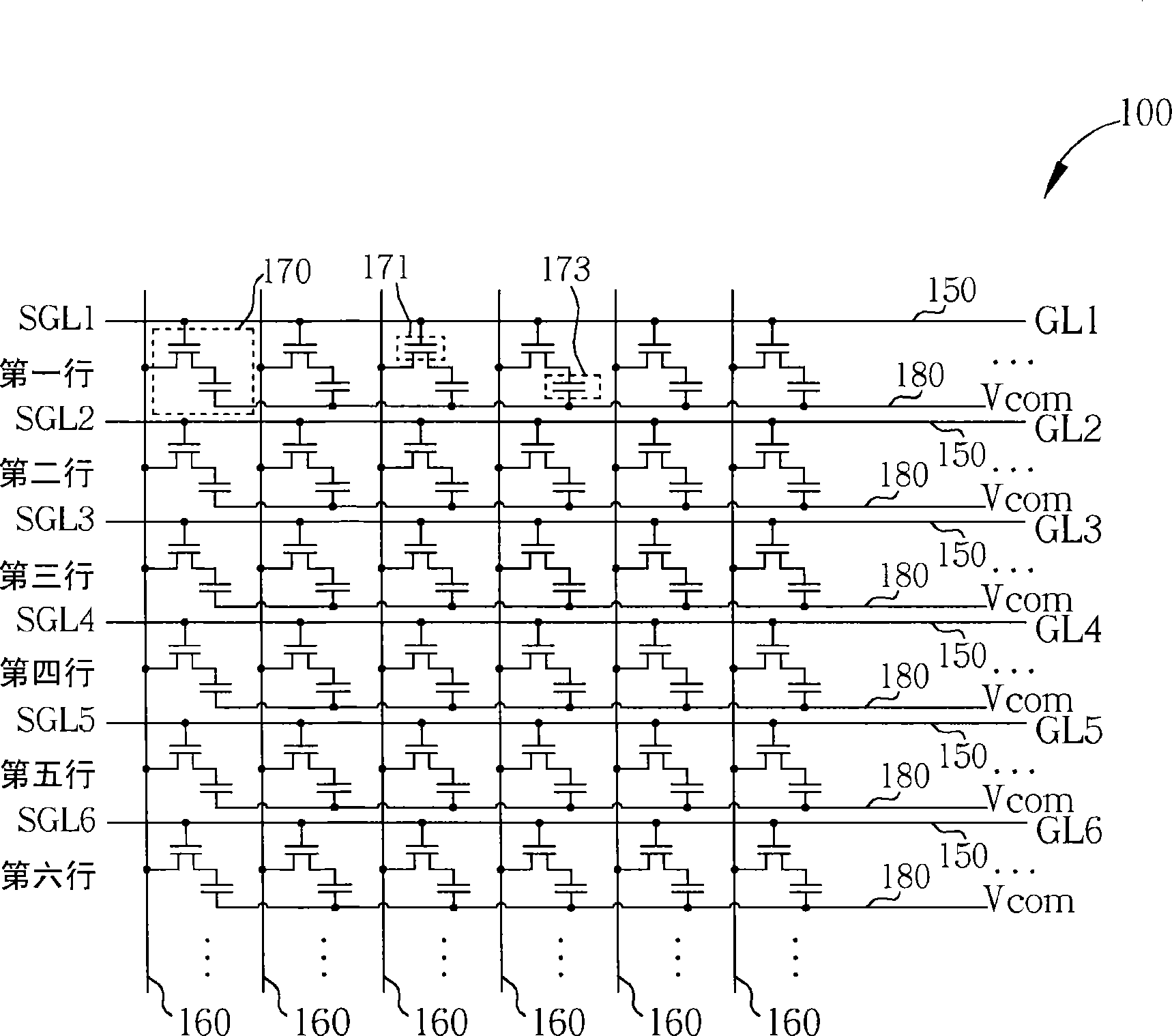
[0060] Figure 4 It is a schematic diagram of a liquid crystal display device using the row inversion driving method of the present invention. Such as Figure 4 As shown, the liquid crystal display device 400 includes multiple data lines 460, multiple gate lines 450, multiple common electrode lines 480, and multiple rows of pixels, wherein the multiple gate lines 450 are divided into multiple groups of gate lines. For the convenience of explanation, Figure 4 The liquid crystal display device 400 only displays 6 data lines 460, 18 common electrode lines 480, and 18 gate lines 450 (GL1-GL18), and each common e...


PUM


Abstract

The invention discloses a method for driving a liquid crystal display with a plurality of groups of grid lines. The method comprises the following steps that: a plurality of odd grid lines of the first group of grid lines are arranged in an ascending order in a first period of time, the first polarity data is written into a plurality of corresponding pixels by matching a first common voltage; a plurality of even grid lines of the first group of grid lines are arranged in an ascending order in a second period of time, the second polarity data is written into a plurality of corresponding pixelsby matching a second common voltage; a plurality of even grid lines of the second group of grid lines are arranged in a descending order in a third period of time, the second polarity data is writteninto a plurality of corresponding pixels by matching a second common voltage; and a plurality of odd grid lines of the second group of grid lines are arranged in a descending order in a fourth periodof time, the first polarity data is written into a plurality of corresponding pixels by matching the first common voltage. The method can evidently improve the picture quality.

Description

technical field [0001] The present invention relates to a method for driving a liquid crystal display device, in particular to a method for driving a liquid crystal display device based on an interleaved commutation scanning mode of multiple groups of gate lines, which is used to reduce the moiré effect (Mura effect) of the display screen and Improve picture quality. Background technique [0002] The liquid crystal display device is a kind of flat panel display widely used at present, and it has the characteristics of light and thin appearance, power saving and no radiation pollution. The working principle of the liquid crystal display device is to change the arrangement state of liquid crystal molecules in the liquid crystal layer by changing the voltage difference across the liquid crystal layer to change the light transmittance of the liquid crystal layer, and then cooperate with the light source provided by the backlight module to display images. [0003] Generally spea...

Claims


Application Information

Patent Timeline
Patent Type & Authority Patents(China)
IPC IPC(8): G02F1/1362G09G3/36
Inventor 白承丘王仓鸿陈忠君詹功一黎焕欣李忠隆
Owner AU OPTRONICS CORP
Why Eureka
Try Eureka