
Automatic rapid plug-in mechanism

A plug-in mechanism and automatic technology, which is applied in the direction of connection, structural parts, clamping/spring connection, etc., can solve the problems of expanding the mileage, not waterproof, and power loss, etc., to achieve extended mileage, convenient maintenance, Power Saving Effect

Active Publication Date: 2008-10-22
BEIJING INSTITUTE OF TECHNOLOGYGY
View PDF0 Cites 10 Cited by
  • Summary
  • Abstract
  • Description
  • Claims
  • Application Information

AI Technical Summary

Problems solved by technology

The power connection between each battery box is connected with a manual plug and placed at the door on both sides where people can easily access; this will cause many problems such as too long battery connection, large loop voltage drop, small power output, and large power loss.
In addition, the single battery is bare in the metal box, which is not waterproof, dustproof, and shockproof, and is prone to self-discharge, resulting in looseness and contact resistance, which affects the consistency and power output of the battery.
Moreover, the whole box is fixed with bolts, so it cannot be quickly installed and unloaded, and the mileage cannot be extended by quick battery replacement. In particular, organic batteries such as lithium batteries are flammable when misused, and their promotion and use must be compatible with Safety Conditions for Quick Separation of Automobiles
In this way, it is difficult to popularize the lithium battery, a high energy density battery. To solve this technical problem, an automatic quick plug-in mechanism is needed to quickly separate the battery pack from the car. In the past, there was no suitable DC high voltage, high current, The connector of dynamic plugging, for this reason, has proposed the technical scheme of the present invention

Method used


Image

  • Automatic rapid plug-in mechanism
  • Automatic rapid plug-in mechanism
  • Automatic rapid plug-in mechanism

Examples


Embodiment Construction

[0027] The automatic quick plug-in mechanism of the present invention will be described in detail below with reference to the accompanying drawings.

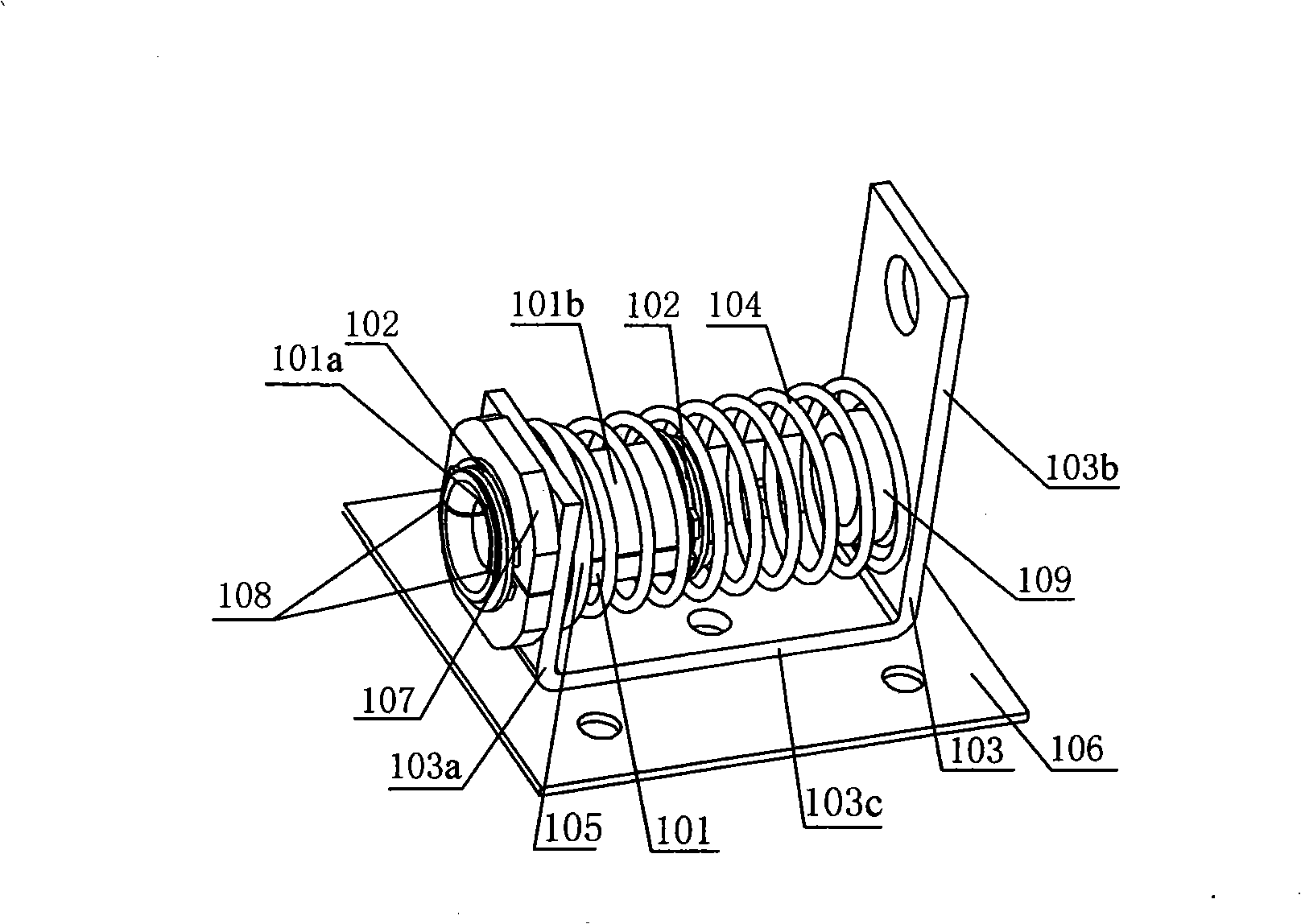
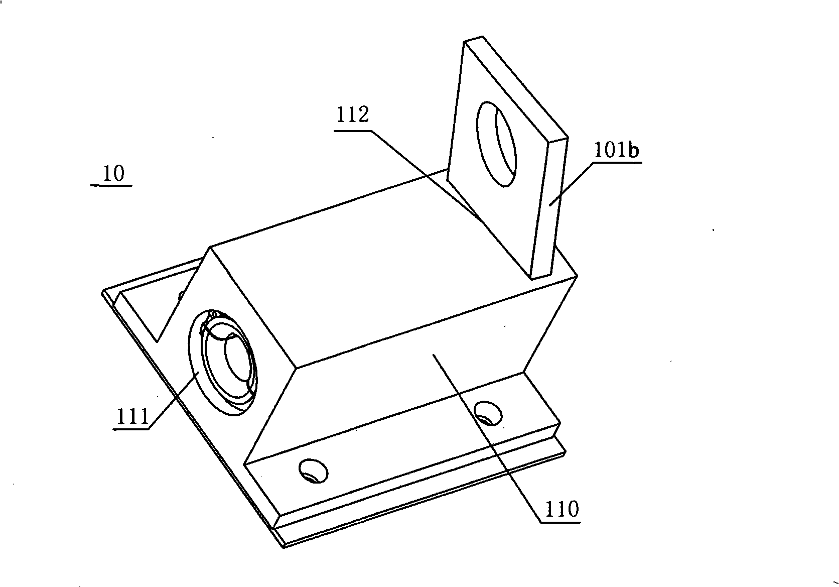
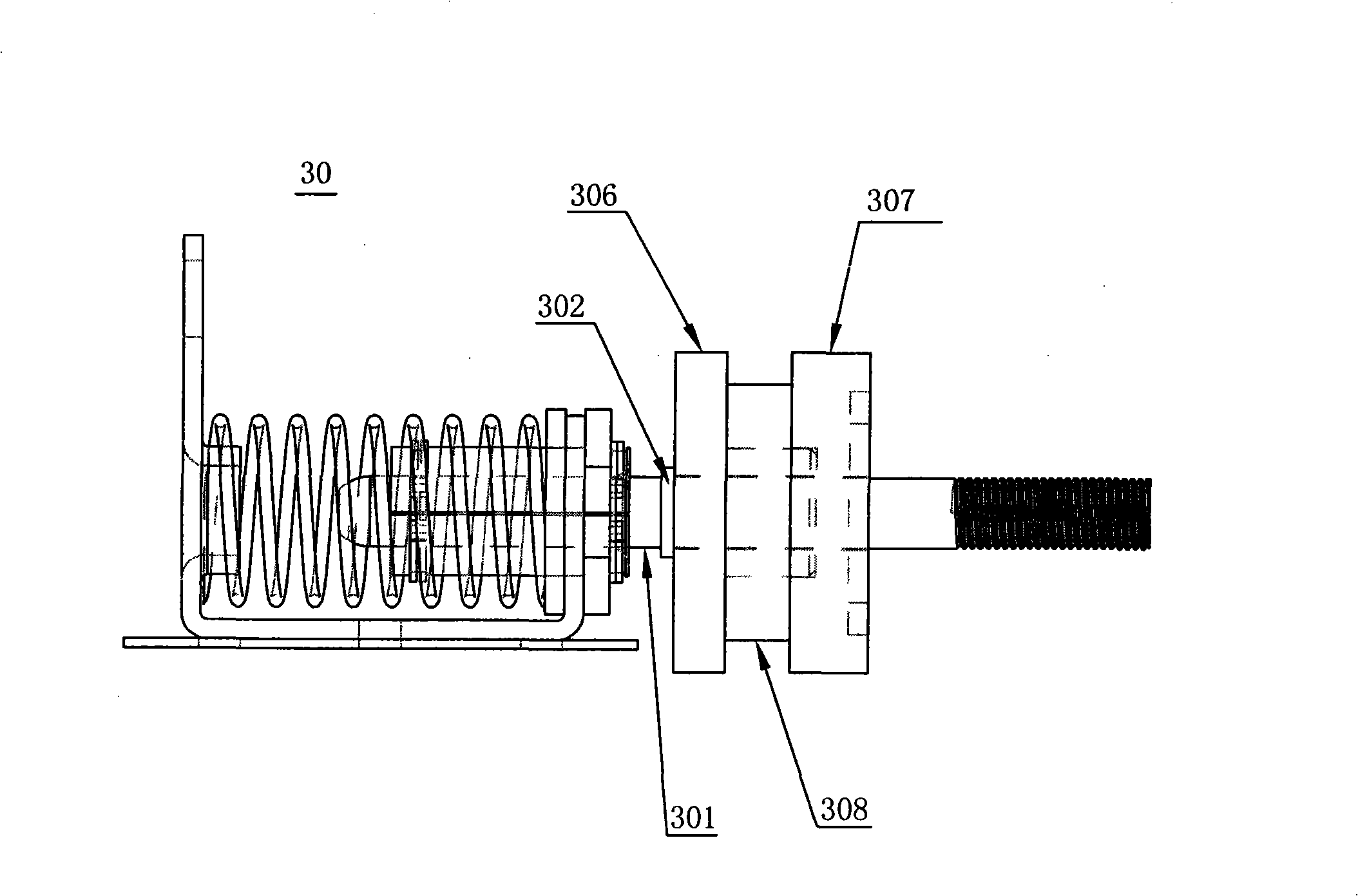
[0028] figure 1 Shows the jack assembly 10 of the automatic quick-connect mechanism 1 according to the first embodiment of the present invention. Wherein, the jack assembly 10 has certain expansion and retraction capabilities. Such as figure 1 As shown, the socket assembly 10 includes a socket body 101, which is a hollow cylinder, and a cutout 108 is formed on the wall of the cylinder along its central axis. And a hoop spring 102 is respectively fixed at both ends of the jack body 101 . Preferably, the inner diameter of the hoop spring 102 is equal to or slightly larger than the outer diameter of the socket body 101 . In this way, when the plug body 301 whose end surface diameter is larger than the inner diameter of the outer port of the jack body 101 is inserted into the jack body 101, the jack body 101 can expand, and unde...


PUM


Abstract

The invention relates to an automatic quick plug connection mechanism, which comprises at least two jack components arranged on a cell unit rear end face, which is inserted into a cell box, of a cell unit, and at least tow plug components arranged on a side face, opposite to the cell unit rear end face, of the inside of the cell box, wherein the jack components are capable of clamping elastically and rebounding, and the plug components are capable of centering elastically; the plug components can automatically insert into the jacks when the cell unit is pushed into the cell box like a drawer. With the function and fit of the plug components and the jack components, the difference in coaxiality of the jack and plug components generated in the manufacture and assembly process can be absorbed, which contributes to the elimination of the vibration of the cell unit relative to a cell box body and the vibration of the cell box body to a vehicle body; therefore, the safe output of the power of the cell unit through the plug component can be guaranteed. The automatic quick plug connection mechanism meets the condition of automatic quick plug connection of electric devices under high voltage and heavy current and realizes the quick assembly and quick disassembly of the cell unit.

Description

technical field [0001] The invention relates to an automatic fast plug-in mechanism suitable for the technical field of electric vehicles. More specifically, it relates to an automatic quick plug-in mechanism applied to battery packs and battery boxes of electric vehicles. Background technique [0002] Limited oil resources and increasingly prominent environmental pollution problems have drawn more and more attention from the society to electric vehicles, and electric vehicles have become the development direction of future automobiles. One of the core technologies of electric vehicles is the energy storage and supply system. Solving the use of battery technology has become the technical key to the industrialization of electric vehicles. The battery monomers of existing electric vehicles (such as buses) are connected in series through wires, and the monomers are only connected with wires and are bare-packed in metal boxes. The power connection between each battery box is c...

Claims


Application Information

Patent Timeline
Patent Type & Authority Applications(China)
IPC IPC(8): H01M2/20H01R4/48H01R13/629H01M50/244H01M50/249H01M50/296H01M50/503
CPCY02E60/10
Inventor 王震坡林程孙逢春马军
Owner BEIJING INSTITUTE OF TECHNOLOGYGY
Learn More