Supercharge Your Innovation With Domain-Expert AI Agents!

Switch control circuit and its control method

A technology for controlling circuits and circuits, applied in the direction of electrical components, sustainable manufacturing/processing, high-efficiency power electronic conversion, etc., can solve problems such as reducing the power efficiency of power converters

Active Publication Date: 2008-10-22
SYST GEN
View PDF1 Cites 8 Cited by
  • Summary
  • Abstract
  • Description
  • Claims
  • Application Information

AI Technical Summary

Problems solved by technology

[0002] High current demands usually reduce power converter power efficiency

Method used


Image

  • Switch control circuit and its control method
  • Switch control circuit and its control method
  • Switch control circuit and its control method

Examples


Embodiment Construction

[0022] It must be noted here that the different embodiments or examples presented in the following disclosure are used to illustrate different technical features disclosed in the present invention, and the specific examples or arrangements described are used to simplify the present invention. It is not intended to limit the invention. In addition, the same reference numerals and symbols may be used repeatedly in different embodiments or examples, and these repeated reference numerals and symbols are used to describe the content disclosed in the present invention, rather than to represent differences between different embodiments or examples. Relationship.

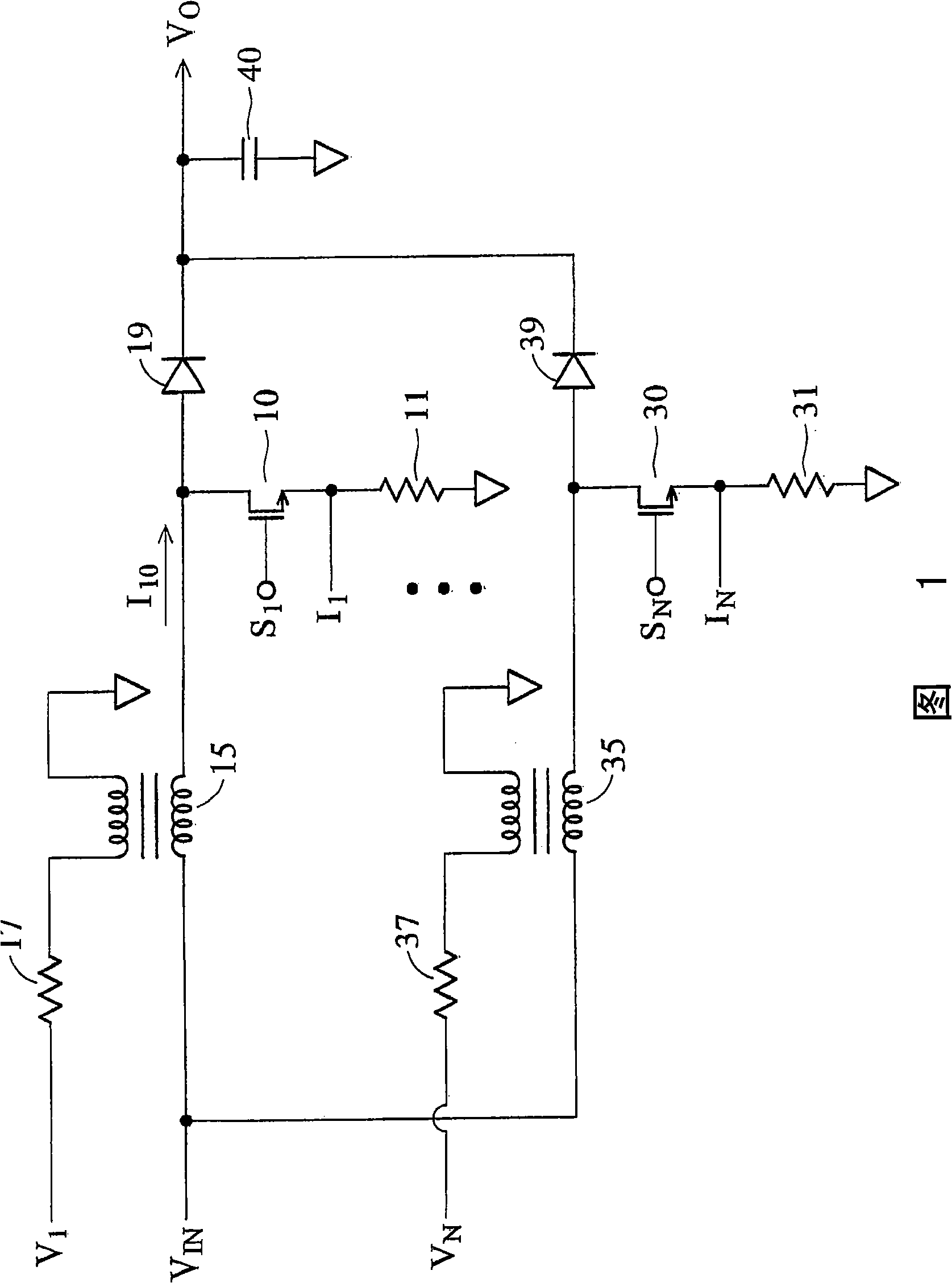
[0023] FIG. 1 shows a preferred embodiment of the present invention applied to a parallel PFC converter, where the first power converter includes a transistor 10 , an inductor 15 , and a rectifier 19 . The first switching signal S 1 The coupling transistor 10 is used for switching the inductor 15 . Rectifier 19 and capac...


PUM


Abstract

A converting control circuit for a power factor correction (Power Factor Correction, PFC) converter is provided. The converting control circuit comprises a PFC control circuit, a phase position detecting circuit, and a starting time adjusting circuit. The PFC control circuit couples a first inductance and the output end of the power factor correction converter for receiving the first inductance signal and a feedback signal to generate a first converting signal; the first inductance signal is used for converting the first inductance to process the power factor correction; and the first inductance signal and the relevant demagnetization for the first inductance signal; the phase position detecting circuit detects the first converting signal and the second inductance signal to generate a starting signal and a phase-locking signal; the starting signal is used for enabling a second converting signal with energy; the second converting signal converts the second inductance and the second inductance signal and the relevant demagnetization for the second inductance signal; the starting time adjusting circuit adjusts the starting time of the second converting signal according to the second converting signal.

Description

【Technical field】 [0001] The present invention relates to a switching power converter, especially to a control circuit of a power factor correction (Power Factor Correction, PFC) converter. 【Background technique】 [0002] The high current demand usually reduces the power efficiency of the power converter. The power loss of the power converter and its current are exponentially proportional to the following equation (1): [0003] P LOSS =I 2 ×R-------------------------------------(1) [0004] where I is the switching current of the power converter, and R is the impedance of the switching component, which can be, for example, the equivalent impedance of a capacitor or a resistor. [0005] Because of the aforementioned problems, a parallel connection technique has been developed to reduce the power consumption of the power converter. A power factor correction (Power Factor Correction, PFC) converter is used to improve the power factor of an AC power supply. The detailed te...

Claims


Application Information

Patent Timeline
Patent Type & Authority Applications(China)
IPC IPC(8): H02M1/42
CPCH02M3/1584H02M1/4225H02M2003/1586Y02B70/126Y02B70/10Y02P80/10H02M3/1586
Inventor 杨大勇
Owner SYST GEN
Features
  • R&D
  • Intellectual Property
  • Life Sciences
  • Materials
  • Tech Scout
  • Unparalleled Data Quality
  • Higher Quality Content
  • 60% Fewer Hallucinations
Learn More