
Impulse magnetic valve for removing dust and clearing ash

A technology of pulse solenoid valve and solenoid control valve, applied in valve details, valve device, valve operation/release device, etc., can solve the problems of failure, large energy loss, high processing cost, reduce manufacturing cost and save compressed gas , the effect of improving reliability

Inactive Publication Date: 2011-01-26
WUHAN HUABAO TECHN ENG
View PDF0 Cites 0 Cited by
  • Summary
  • Abstract
  • Description
  • Claims
  • Application Information

AI Technical Summary

Problems solved by technology

[0002] The current pulse solenoid valves used for dust removal and dust removal, especially the pulse solenoid valves used for dust removal on the bag filter, are mostly diaphragm structures. Due to the long path of the pilot hole and small aperture, it is easy to block the pulse solenoid valve. Failure, coupled with the limited life of the diaphragm, makes the service life of the pulse solenoid valve too short
The foreign advanced piston pilot valve has a long service life, but its first-level pilot part always has a diaphragm structure, so it also has the defect of easy clogging and failure. The cost is high, and it is difficult to guarantee its processing quality. Due to processing quality problems, for example, when the parallelism error between the end surface of the blowing pipe and the bottom surface of the pulse solenoid valve piston is 0.5mm (this error is difficult to guarantee for steel structure weldments), resulting in The gas loss is more than twice the effective gas consumption, resulting in excessive energy loss

Method used


Image

  • Impulse magnetic valve for removing dust and clearing ash
  • Impulse magnetic valve for removing dust and clearing ash
  • Impulse magnetic valve for removing dust and clearing ash

Examples


Embodiment Construction

[0017] This embodiment is used to explain the claims of the present invention, and the protection scope of the present invention is not limited to the following structures.

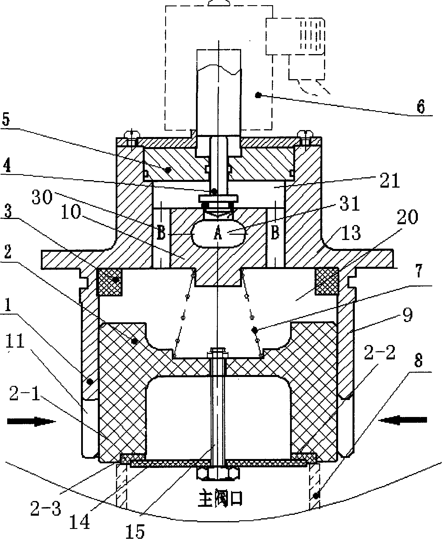
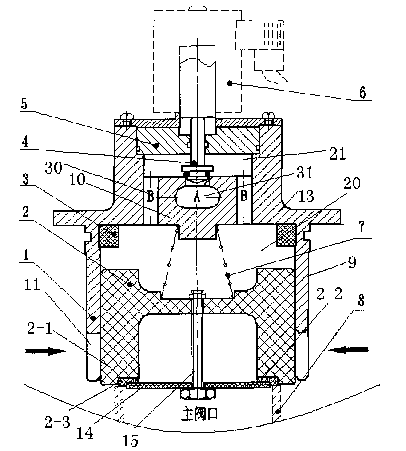
[0018] like figure 1 As shown, the valve body 1 has an upper and lower two-layer structure, forming two upper and lower cavities, that is, two upper and lower cavities; the lower cavity 20 is composed of a lower valve body wall 9 and a partition 10, and the valve body wall 9 is provided with a blowing groove 11 , The blowing grooves 11 are evenly opened along the circumference, and the number of spraying grooves 11 is set according to specific requirements.

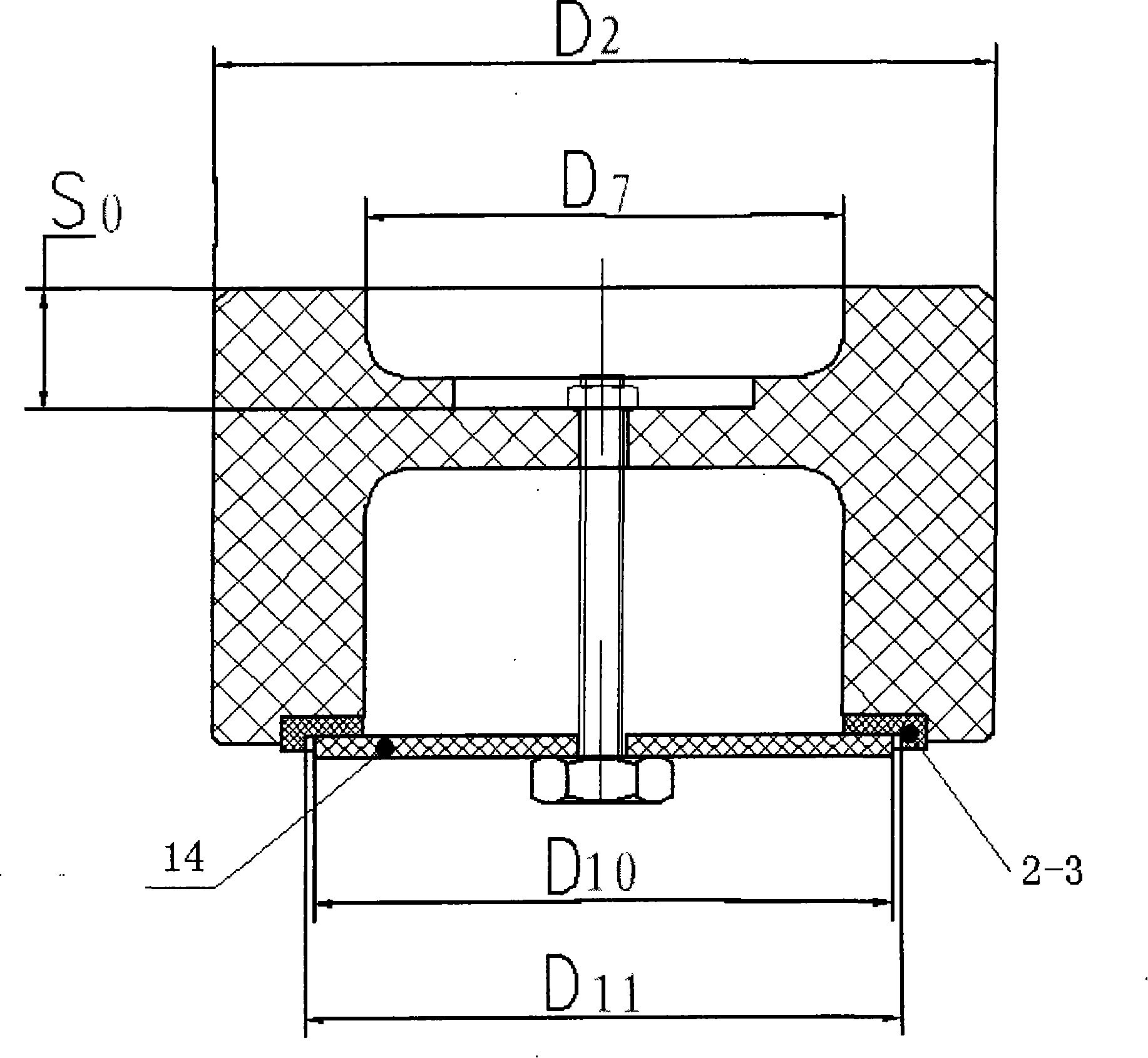
[0019] The lower cavity 20 is provided with a piston assembly 2, the piston assembly 2 includes a piston 2-1, a seal groove 2-2 is arranged at the opening of the piston 2-1, and a soft seal 2-3 is arranged in the seal groove 2-2, A pressing plate 14 connected with the piston, the pressing plate 14 is connected with the piston through a bolt 15, and ...


PUM

PropertyMeasurementUnit
depthaaaaaaaaaa

Abstract

The invention discloses a pulse electromagnetic valve for dedusting and deashing, comprising a valve body; wherein, a blowing trough is arranged on a wall of the valve body; a piston group used for controlling the make-and-break of the blowing trough is arranged in a lower cavity inside the wall of the valve body; the wall of the valve body also comprises an upper cavity; a partition wall is arranged between the upper cavity and the lower cavity, and the partition wall is opened with a through hole which is communicated with the upper cavity and the lower cavity; the upper cavity is communicated with an atmospheric passage; a solenoid electric valve for controlling the make-and-break of the upper cavity and the atmospheric passage is arranged on the upper cavity. The invention has the advantages of simple structure, convenient installation and noleakage, thereby greatly reducing the manufacturing cost of a dedusting gas pocket, improving the dependability and achieving world leading level.

Description

technical field [0001] The invention belongs to a control valve, in particular to a pulse electromagnetic valve used for cleaning dust on a bag filter. Background technique [0002] The current pulse solenoid valves used for dust removal and dust removal, especially the pulse solenoid valves used for dust removal on the bag filter, are mostly diaphragm structures. Due to the long path of the pilot hole and small aperture, it is easy to block the pulse solenoid valve. Failure, coupled with the limited life of the diaphragm, makes the service life of the pulse solenoid valve too short. The foreign advanced piston pilot valve has a long service life, but its first-level pilot part always has a diaphragm structure, so it also has the defect of easy clogging and failure. The cost is high, and it is difficult to guarantee its processing quality. Due to processing quality problems, for example, when the parallelism error between the end surface of the blowing pipe and the bottom s...

Claims


Application Information

Patent Timeline
Patent Type & Authority Patents(China)
IPC IPC(8): B01D46/04B01D46/42F16K31/06
Inventor 吴克俭付桂林杜建敏陈云
Owner WUHAN HUABAO TECHN ENG
Learn More