Cantilever member and manufacturing method thereof, magnetic head tab combination and disk drive unit

A disk drive and cantilever technology, which is applied to align the tracks on the disk, the hydrodynamic spacing of the head, and the direction of the support head. Write performance, reduce pitch and roll attitude changes, and simplify the effect of the process

Active Publication Date: 2008-10-29
SAE MAGNETICS (HK) LTD
View PDF0 Cites 0 Cited by
  • Summary
  • Abstract
  • Description
  • Claims
  • Application Information

AI Technical Summary

Problems solved by technology

However, in this connection method, when the flexible member 40 is connected to the magnetic head slider 2 at the corresponding front position of the flexible member, it is necessary to additionally provide connection contacts 41, 41 ′ at the corresponding front position of the flexible member. The connection contacts 41, 41' on the front side of the part are independently manufactured with the trace pattern 43 and the connection contacts 42A-42D, and the connection contacts 41, 41' are placed on the flexible part 40 by optical processing (photo process) When it is connected, the slight positional alignment error of the connection contacts 41 and 41' will cause a large change in the connection force, and cause the static pitch attitude (PSA, pitch static attitude) and static roll attitude (RSA, RSA, roll static attitude) changes due to changes in the connection position, and accordingly, changes in pitch and roll attitudes will cause changes in the flying height of the magnetic head, which weakens the flying performance of the magnetic head and data read and write performance

Method used


Image

  • Cantilever member and manufacturing method thereof, magnetic head tab combination and disk drive unit
  • Cantilever member and manufacturing method thereof, magnetic head tab combination and disk drive unit
  • Cantilever member and manufacturing method thereof, magnetic head tab combination and disk drive unit

Examples


Embodiment Construction

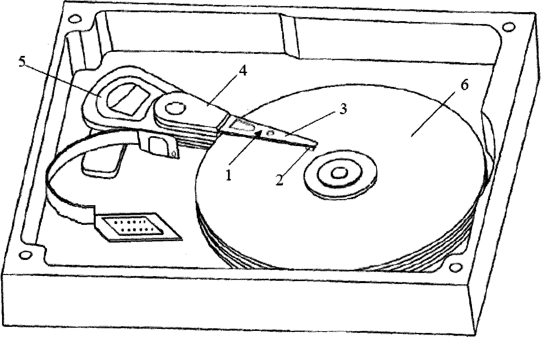
[0052] Embodiments of the present invention will now be described with reference to the drawings, in which like reference numerals represent like elements. Refer to the accompanying drawings in detail below, Figure 4 It is a perspective view of the disk drive unit of the present invention, and FIG. 5 is a partially enlarged perspective view of the head gimbal assembly of the disk drive unit. In order to facilitate the understanding of the construction and configuration principles of the HGA and the disk drive unit, known components and characteristic components of the present invention will be described below.

[0053] Such as Figure 4 As shown, the disk drive unit includes a set of disks 904 spaced apart from each other and a HGA with a HGA 901 . The disk 904 rotates around a spindle motor. The HGA 901 includes a HGA 100 and a suspension 200 . The HGA 901 is connected to the driving arm 903 . The head actuator arm assembly rotates around an axis of the actuator arm 903 a...


PUM


Abstract

The invention discloses a cantilever part used for supporting a magnetic head sliding block. The cantilever part comprises a flexible part, a compound circuit arranged on the flexible part, a front connecting contact and a back connecting contact of the flexible part. The front connecting contact of the flexible part is arranged on a position of the flexible part corresponding to the front side of the magnetic head sliding block, and the front connecting contact is connected with one circuit. The back connecting contact of the flexible part is arranged on a position of the flexible part corresponding to the tail side of the magnetic head sliding block and is connected with one circuit. The front and back connecting contacts of the flexible part can be integrated for forming together with the circuit and can be simultaneously arranged on the flexible part so as to simplify the manufacturing process and avoid correcting of connecting positions, thus guaranteeing the connecting force and connection position between the magnetic head sliding block and the cantilever part are not changed to further guarantee better state of the sliding block of the magnetic head. The invention simultaneously discloses a magnetic head sheet unit provided with the cantilever part, a magnetic head driving unit and a manufacturing method for the cantilever part.

Description

technical field [0001] The present invention relates to an information recording disk drive unit and its constituent elements, in particular to a suspension that connects a magnetic head slider in a single manner, a magnetic head flap assembly and a disk drive with the suspension, and also relates to the process for manufacturing the suspension method. Background technique [0002] A disk drive system is an information storage device that uses magnetic media to store data and selectively reads data from or writes data to the magnetic media with a movable read / write head positioned over the magnetic media superior. [0003] Referring to FIG. 1 , a disk drive typically includes several disks 6 connected to a spindle motor for rotation. A corresponding HGA comprising a head gimbal assembly (HGA) 1 is suspended on the surface of the magnetic disk 6 . The HGA 1 is connected and installed on the driving arm 4 . A voice coil motor (VCM) 5 is connected to the driving arm 4 to co...

Claims


Application Information

Patent Timeline
Patent Type & Authority Applications(China)
IPC IPC(8): G11B5/56G11B5/596G11B5/60G11B21/20
Inventor 冯先文何耀诚
Owner SAE MAGNETICS (HK) LTD
Why Eureka
Try Eureka