

Engine controller, controller of engine and hydraulic pump, and engine, hydraulic pump and controller of generator motor
A technology of generator motor and control device, which is applied in the direction of engine control, machine/engine, electrical control, etc., can solve the problems of pump efficiency, fuel consumption and noise deterioration, etc.
Inactive Publication Date: 2008-10-29
KOMATSU LTD
View PDF2 Cites 16 Cited by
- Summary
- Abstract
- Description
- Claims
- Application Information
AI Technical Summary
Problems solved by technology
Therefore, there is a problem that the engine 2 does not operate in the low rotation range unless it is set by the fuel dial, and the pump efficiency, fuel consumption, and noise deteriorate.
Method used
View moreImage
Smart ImageViewing Examples

Examples
no. 1 Embodiment
no. 2 Embodiment
no. 3 Embodiment
Login to View More PUM
 Abstract
A working machine is operated as intended by an operator with good response and with enhanced engine efficiency, pump efficiency, and the like. A first engine target speed of rotation ncom1 conforming to a current pump target delivery flow rate Qsum is set, and when a decision is made that the current pump target delivery flow rate Qsum is higher than a predetermined flow rate (e.g. 10 (L / min)), a decision is made that operating means (41-44) are switched from nonoperating state to operating state, and a speed of rotation nM (e.g. 1400 rpm) higher than the engine idle speed of rotation nL is set as a second engine target speed of rotation ncom2. If the second engine target speed of rotation ncom2 is higher than the first engine target speed of rotation ncom1, engine speed of rotation is controlled to attain the second engine target speed of rotation ncom2.
Description
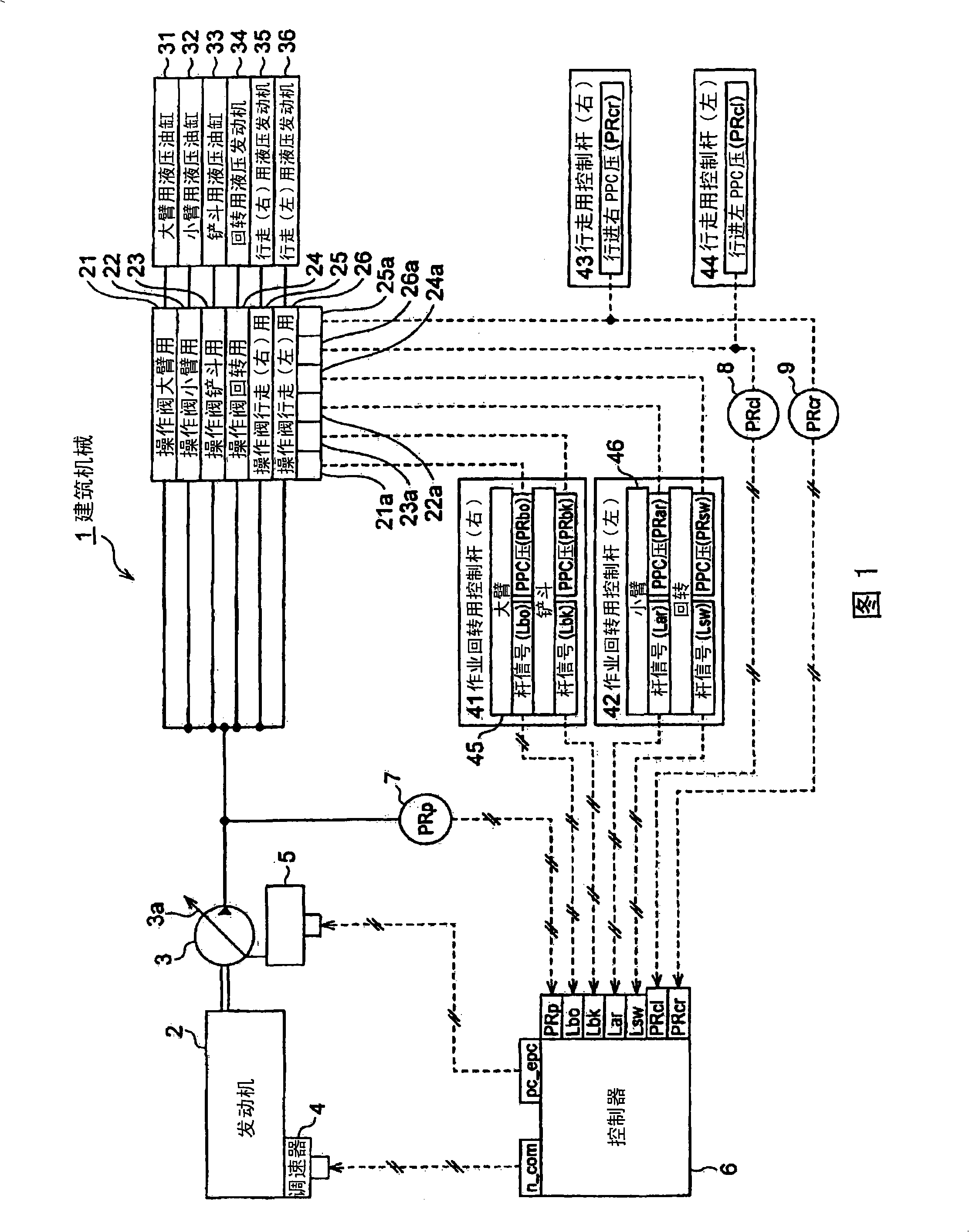
Engine control devices, engine and hydraulic pump control devices, and engine, hydraulic pump and generator motor control devices technical field The present invention relates to a control device for an engine, a control device for an engine and a hydraulic pump, and a control device for an engine, a hydraulic pump, and a generator motor, and particularly to a control device used when the hydraulic pump is driven by the engine. Background technique Diesel engines are installed in construction machines such as hydraulic excavators, bulldozers, dump trucks, and wheel loaders. The configuration of a conventional construction machine 1 is schematically described with reference to FIG. 1 . As shown in FIG. 1 , a diesel engine 2 is used as a driving source to drive a hydraulic pump 3 . The hydraulic pump 3 is a variable capacity type hydraulic pump, and the capacity q (cc / rev) is changed by changing the inclination angle of the swash plate 3a or the like. The pressure oil disc...
Claims
Login to View More Application Information
Patent Timeline
 IPC IPC(8): F02D29/04F02D29/00E02F9/20F02D45/00
Inventor 森永淳河口正井上宏昭
Owner KOMATSU LTD