
High efficiency construction method of cast-in-situ hollow core floor slab

A construction method and technology for hollow-core slabs, which are applied to slabs, building components, buildings, etc., can solve problems such as application limitations of cast-in-place hollow slabs with dark ribs, poor economic and technical indicators, and difficult positioning of formwork.

Inactive Publication Date: 2008-11-05
高家榕
View PDF0 Cites 3 Cited by
  • Summary
  • Abstract
  • Description
  • Claims
  • Application Information

AI Technical Summary

Problems solved by technology

Therefore, the thin-walled hollow boxes made of cement that are commonly used today cannot meet the needs of engineering construction very well, which limits the application of cast-in-place hollow slabs with concealed ribs.
However, the light-weight filling materials in the existing hollow members have poor economic and technical indicators, and are not easy to locate on the formwork

Method used


Image

  • High efficiency construction method of cast-in-situ hollow core floor slab
  • High efficiency construction method of cast-in-situ hollow core floor slab
  • High efficiency construction method of cast-in-situ hollow core floor slab

Examples


specific Embodiment approach 1

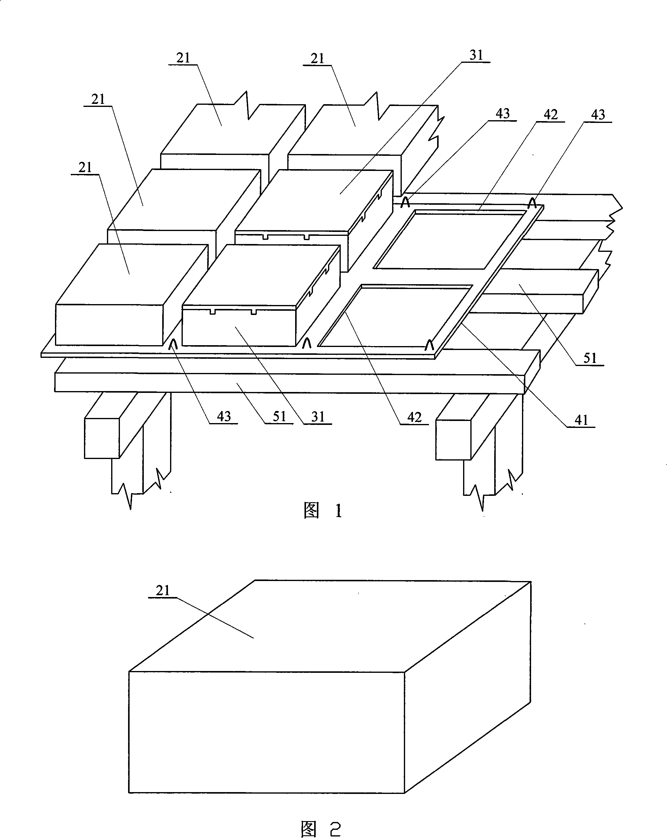
[0005] Specific embodiment one: (referring to Fig. 1) the construction method of this embodiment is realized by following steps: one, set up temporary support beam 51; Line 42, the ceiling 41 of concave-convex line 42 periphery is provided with suspension hook 43; Three, above temporary support beam 51, be covered with ceiling 41 without gap; Block 21 or the assembled hollow box 31 of magnesite material, the assembled hollow box 31 of the aerated block 21 of magnesite material or magnesite material all cooperates with the concave-convex line 42 of ceiling 41; five, in the magnesite material In the gap between the aerated block 21 or the assembled hollow box 31 of magnesite material, put steel bars and bind the steel bars; six, pour concrete.

specific Embodiment approach 2

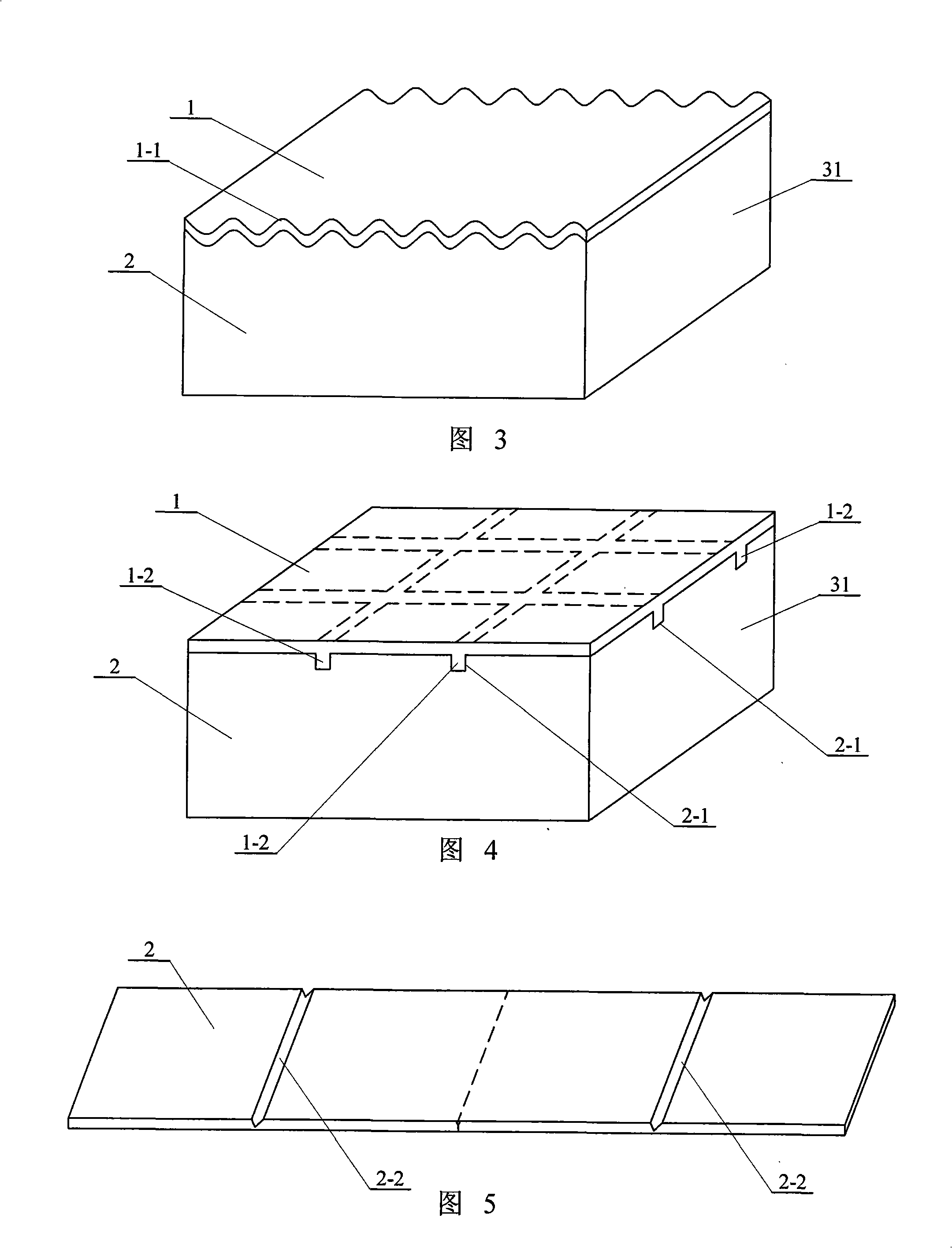
[0006] Embodiment 2: (see FIGS. 2 to 4 ) The assembled hollow box 31 in this embodiment includes an upper cover 1 and a rectangular tube 2 , and the lower side of the upper cover 1 fits with the upper end of the rectangular tube 2 .

specific Embodiment approach 3

[0007] Specific embodiment three: (see FIG. 3 ) The upper cover 1 of this embodiment is in a wave shape 1-1. The strength of the corrugated loam cake 1 can be greatly improved, and can meet the technical requirements of the construction load on the hollow member. Others are the same as in the second embodiment.


PUM


Abstract

An efficient construction method of cast-in-situ hollow floor relates to a construction method of the cast-in-situ hollow floor. The invention aims to solve problem that the damage ratio in producing, conveying and construction process is high and a filler element on a molding plate is not easy to position by a thin wall hollow box that mainly adopts cement material. The invention is provided with a plurality of ceilings without gap at upper side of a temporary supporting beam; a gas-entrapping block of magnestite material or an assembling hollow box placing the magnestite material is placed on the ceiling as the molding plate. The gas-entrapping block of magnestite material or an assembling hollow box placing the magnestite material matches a concave and convex line of the ceiling. The construction method of the invention places the gas-entrapping block of magnestite material or the assembling hollow box placing the magnestite material in site, which implements a batch of works in a large scale. The temporary molding plate for the exchange in site is saved and the filler element is easy to fix on the molding plate. The sunshade is not need to be plastered after detached. Self-weight of the floor is light, which saves a lot of reinforcing steel bar and concrete and other construction materials.

Description

technical field [0001] The invention relates to a construction method of cast-in-place hollow floor slabs. Background technique [0002] In order to build long-span floor slabs, reduce material consumption and project cost, in recent years many large-span floor slabs have adopted the structure of cast-in-place hollow-core slabs with hidden ribs to form a high hollow rate. This type of hollow floor structure requires the prefabrication of a large number of hollow components that can form a structural hollow cavity. Such hollow components include lightweight fill materials and thin-walled hollow boxes. During construction, the hollow member should meet the technical requirements of having a fixed position and being able to bear the construction load on the hollow member. Existing hollow components have great defects in manufacture and installation. For example, ceramsite blocks, cement aerated blocks, perlite blocks or benzene plates in lightweight filling materials have pro...

Claims


Application Information

Patent Timeline
Patent Type & Authority Applications(China)
IPC IPC(8): E04B5/19E04B5/36
Inventor 高家榕
Owner 高家榕
Learn More