
Combined high-tension current potential transformer

A technology of voltage transformers and current transformers, which is applied in the direction of inductors, transformers, circuits, etc., can solve the problems that cannot be applied to high-voltage and ultra-high-voltage occasions, increase the area occupied by power stations, increase the use and maintenance costs, and achieve significant Economic and social benefits, product cost reduction, good dynamic and thermal stability

Inactive Publication Date: 2010-09-29
徐文
View PDF1 Cites 0 Cited by
  • Summary
  • Abstract
  • Description
  • Claims
  • Application Information

AI Technical Summary

Problems solved by technology

[0002] The high-voltage transformers used on the power grid, especially the transformers with 110KV and higher voltage levels, are all independent structures, that is, the current transformers and voltage transformers are independent individuals, and sufficient installation is required between each transformer on the power station. The insulation space and distance increase the area of ​​the power station many times
At the same time, independent current transformers and voltage transformers also greatly waste manufacturing materials, resulting in increased manufacturing costs, thereby increasing use and maintenance costs
In the prior art, some combined current and voltage transformers are disclosed on the market and in patent documents, but they are all used when the system voltage is not very high, and all are independent current transformers and independent voltage transformers Simple combination and patchwork, not suitable for high pressure and ultra high pressure occasions

Method used


Image

  • Combined high-tension current potential transformer
  • Combined high-tension current potential transformer
  • Combined high-tension current potential transformer

Examples


Embodiment Construction

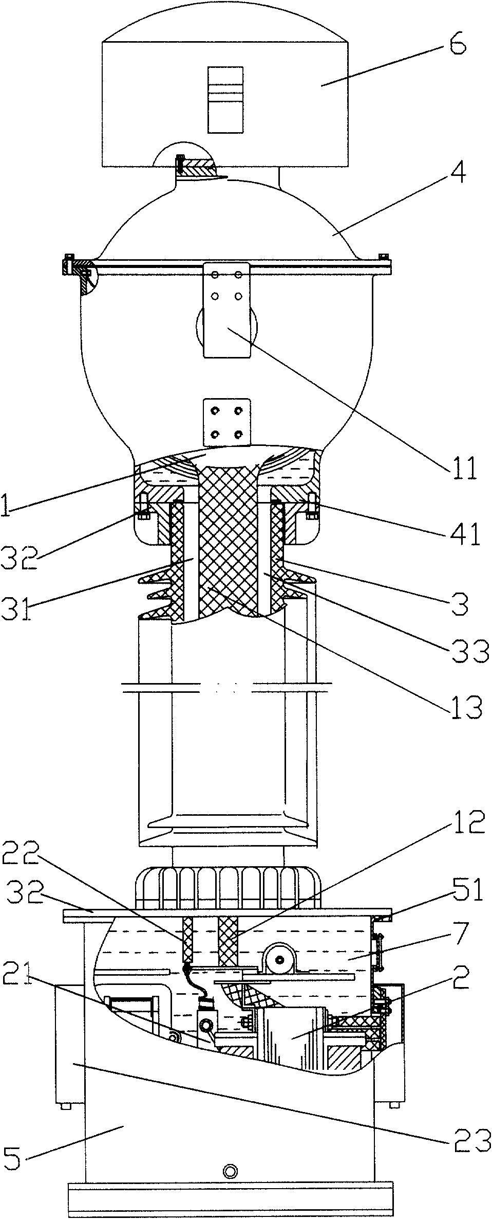
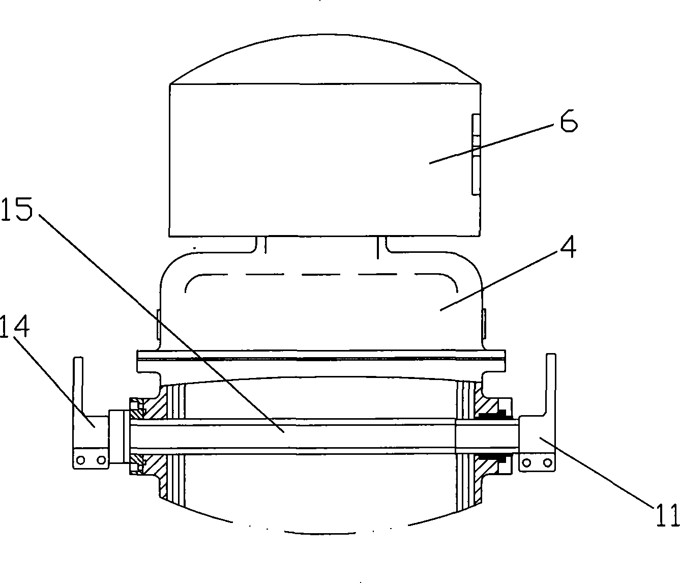
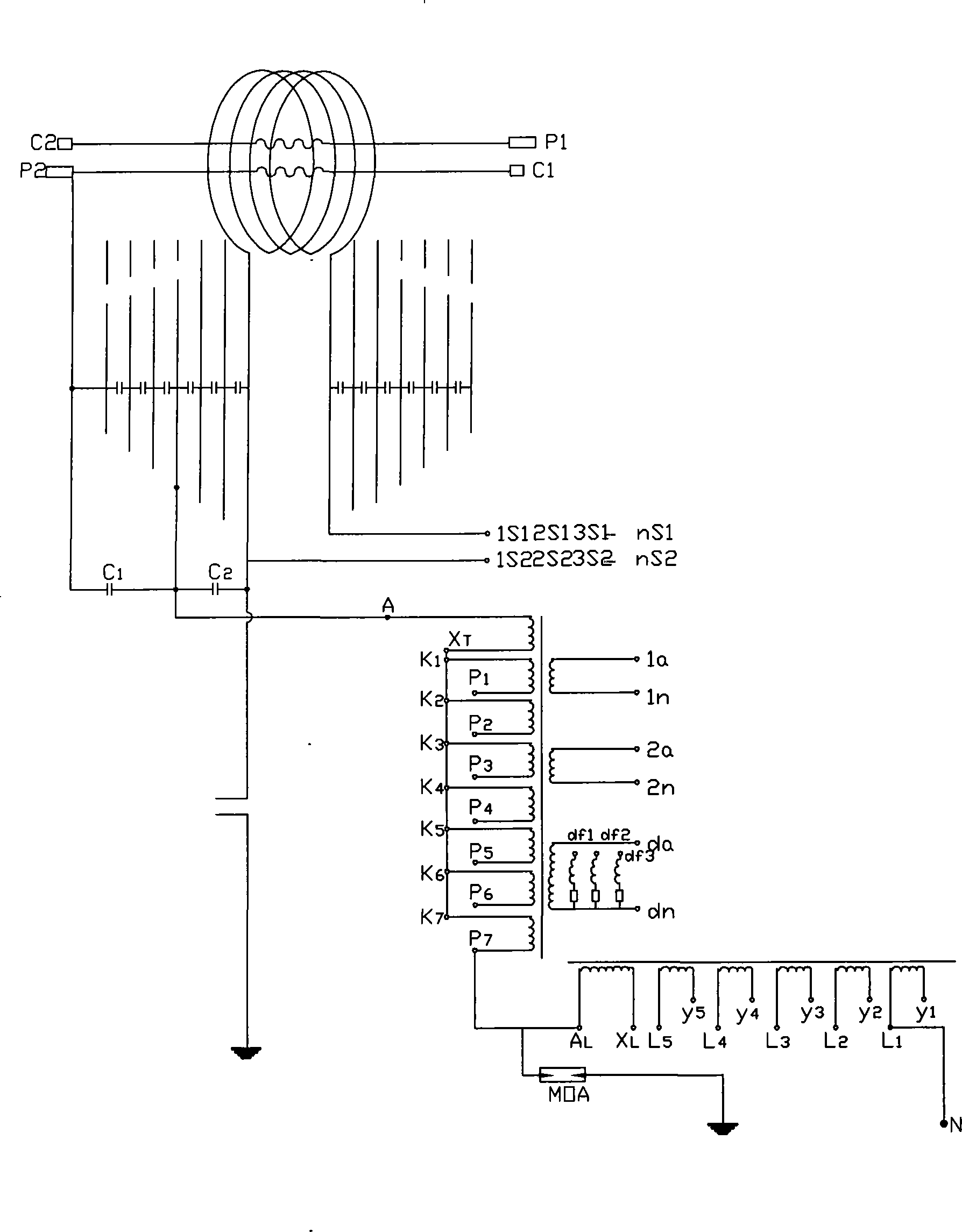
[0019] figure 1 It is a structural schematic diagram of the present invention, figure 2 for figure 1 Partial side sectional view, as shown in the figure: the combined high-voltage current and voltage transformer of this embodiment includes a current main body 1 and a voltage main body 2 arranged as one, and the current main body 1 is a capacitive inverted current transformer, which is provided with a primary current Input terminal 11 and primary current output terminal, two capacitive screens are arranged outside the secondary winding of current transformer 1 and its leads and wrapped with polypropylene film; voltage main body 2 includes intermediate transformer 21, and the primary voltage of intermediate transformer 21 is drawn from the current transformer The tap 13 in the corresponding main capacitance screen of 1 makes the voltage main body 2 constitute a capacitive voltage transformer, and the primary lead wire 22 connected with the intermediate capacitor tap 13 of the ...


PUM


Abstract

The invention discloses a combination type high voltage current voltage transformer, comprising a current main body and a voltage main body as an integer, wherein the current main body is the current transformer provided with a primary current input end and a primary current output end. The main insulation of the current transformer is the capacitance type structure. The voltage main body includes a middle transformer, the primary voltage of which is educed from the middle capacitance tap of the current transformer to make the voltage main body constitute the capacitance type voltage transformer. The secondary current of the current transformer and the secondary voltage of the voltage transformer are respectively educed. The invention realizes that one device completes the two functions of the current transformer and the voltage transformer, meanwhile saves the capacitance voltage divider and the couple capacitor of the capacitance type voltage transformer, which reduces the manufacture cost. The invention has small occupation area, convenient installation and use, low cost, which is used in the high voltage system with marked advantage and the cost is reduced to 50%.

Description

technical field [0001] The invention relates to a transformer used in a power system, in particular to a combined high voltage current voltage transformer. Background technique [0002] The high-voltage transformers used on the power grid, especially the transformers of 110KV and higher voltage levels, are all independent structures, that is, the current transformers and voltage transformers are independent individuals, and sufficient installation is required between each transformer on the power station. The insulation space and distance increase the area occupied by the power station many times. At the same time, independent current transformers and voltage transformers also greatly waste manufacturing materials, resulting in increased manufacturing costs, thereby increasing use and maintenance costs. In the prior art, some combined current and voltage transformers are disclosed on the market and in patent documents, but they are all used when the system voltage is not ve...

Claims


Application Information

Patent Timeline
Patent Type & Authority Patents(China)
IPC IPC(8): H01F38/34H01F38/30H01F38/24
Inventor 徐文
Owner 徐文
Learn More