Magnetic field forming device

A magnetic field and forming body technology, which is applied in the manufacture of inductors/transformers/magnets, electrical components, circuits, etc., can solve problems such as cracks or gaps in the forming body 100, damage to the forming body 100, and prolongation of the production cycle time to achieve production cycle time Effects of shortening time, reducing impact, and suppressing damage

Active Publication Date: 2011-12-28
TDK CORPARATION
View PDF1 Cites 0 Cited by
  • Summary
  • Abstract
  • Description
  • Claims
  • Application Information

AI Technical Summary

Problems solved by technology

However, as a result, the molded body 100 receives an impact or the like, and the molded body 100 may be cracked or chipped.
[0008] In addition, during the ejection operation, the molded body 100 rubs against the surface of the mold, and thus the molded body 100 may be scratched.
[0009] Furthermore, in the magnetic field forming apparatus using a magnetic field, if the ejection (extrusion) of the molded body 100 is not sufficient, the molded body 100 may be pulled back to the cavity 1 side under the action of the magnetic field.
Therefore, in order to reliably eject the molded body 100, if the push-out amount generated by the collet mechanism 3 is increased, there is a problem that the movement stroke of the collet mechanism 3 is increased, thereby prolonging the production takt time. Push the molded body 100 out, the impact on the molded body 100 will increase

Method used


Image

  • Magnetic field forming device
  • Magnetic field forming device
  • Magnetic field forming device

Examples


Embodiment Construction

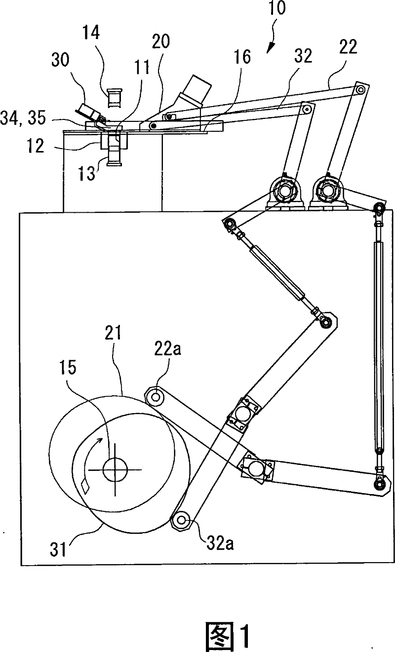
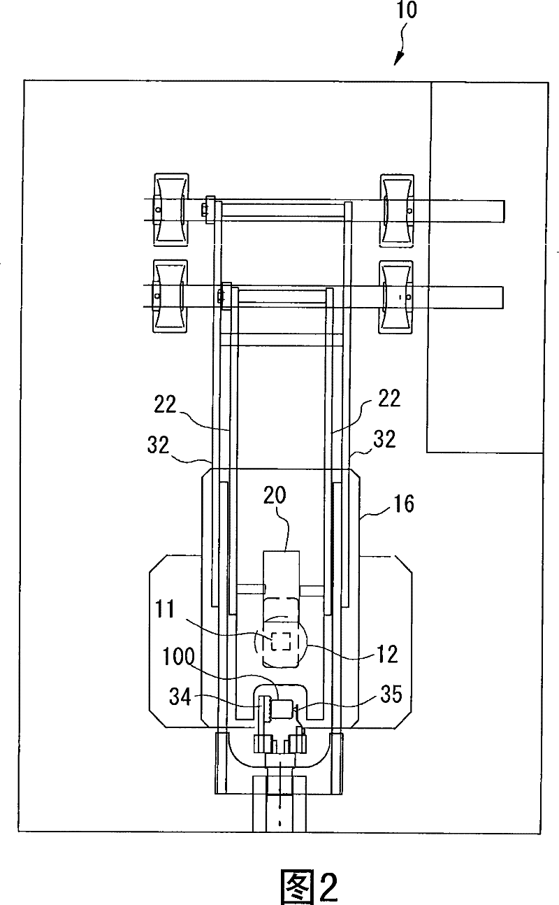
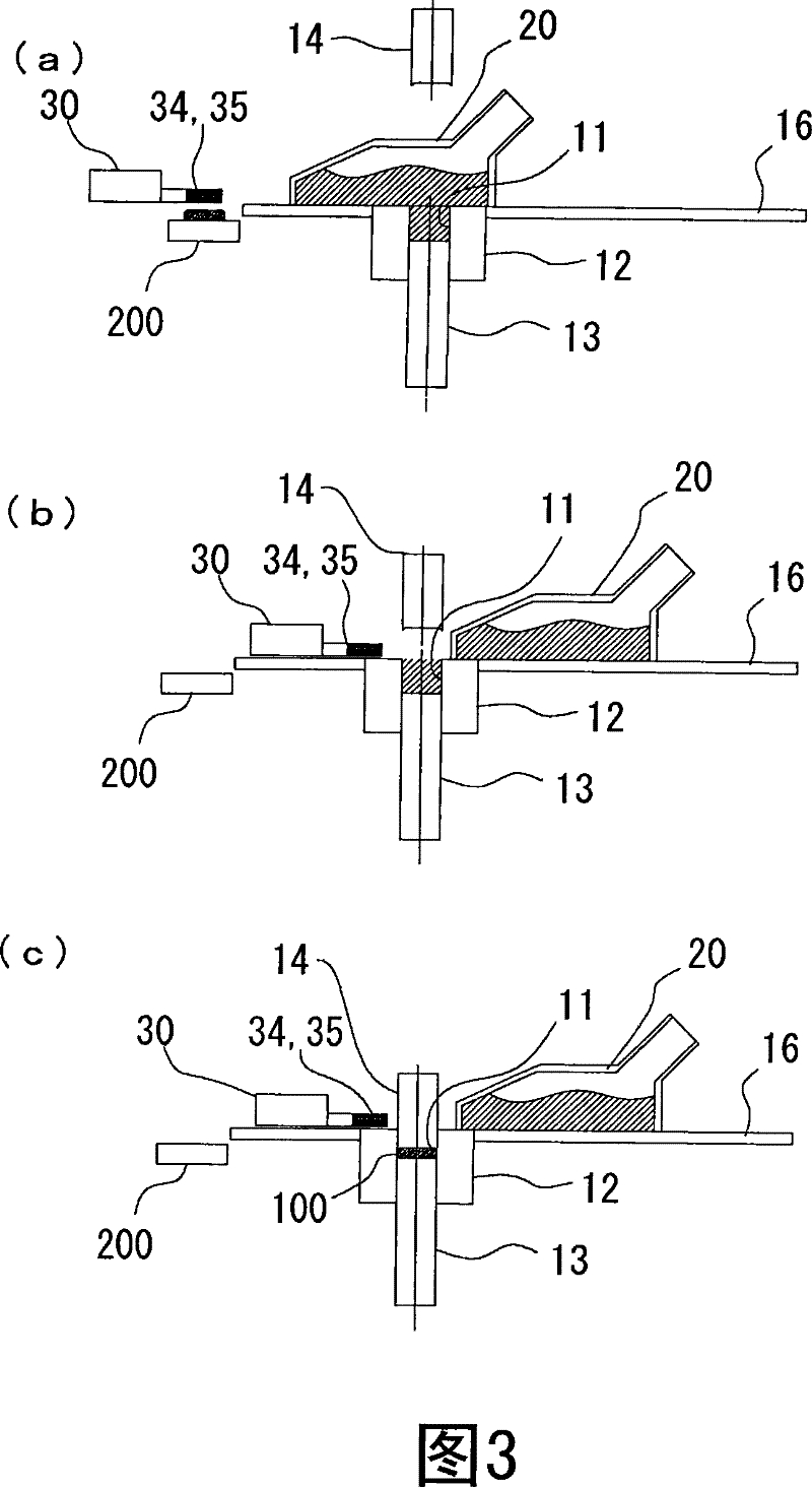
[0040] The present invention will be described in detail below based on the embodiments shown in the drawings.

[0041] The ferrite magnet obtained by sintering the molded body formed by the magnetic field shaping device of this embodiment is preferably set to have ferrite with a hexagonal crystal structure as the main phase. A substance that is at least one element among Pb and must contain Sr is represented by A, and a substance that is at least one element selected from rare earth elements (containing Y) and Bi and that contains La as an essential element is represented by R , and when Co, or Co and Zn is expressed as M, it contains A, R, Fe and M;

[0042] When by formula (1) A 1-x R x (Fe 12-y m y ) z o 19 (x, y, z are the number of moles) when expressing, then satisfy following condition:

[0043] 0.04≤x≤0.5

[0044] 0.04≤y≤0.5

[0045] 0.7≤z≤1.2

[0046] 1≤(x / y)

[0047] Such a ferrite magnet can be produced through the following steps.

[0048]In addition, ...


PUM


Abstract

To provide a magnetic field molding apparatus which certainly sweeps out a compact without having a negative effect on the quality of the compact, and improves productivity. A sweeping mechanism 30 is disposed opposite to a feeder box 20 across a cavity 11 to reduce the amount of move of the sweeping mechanism 30 and suppress the maximum acceleration of a sweeping action. This reduces impact applied on a compact 100 and shortens a cycle time. In addition, it is preferable that the sweeping mechanism 30 and the feeder box 20 are each operated independently to allow the sweeping mechanism 30 to operate properly without being restrained by the operation of the feeder box 20 to further suppress the maximum acceleration of the sweeping action.

Description

technical field [0001] The present invention relates to a powder molding apparatus used when forming ferrite magnets and the like by a dry molding method. Background technique [0002] As magnets, in order to manufacture ferrite (sintered) magnets, which have become the mainstream, raw materials are mixed in a prescribed ratio and calcined to make ferrite, and then the obtained calcined body is pulverized into submicron size, A material powder composed of ferrite particles is obtained. Next, material powder is put into a cavity of a magnetic field forming device, compression-molded in a magnetic field (hereinafter referred to as magnetic field forming) to obtain a molded body, and then the molded body is sintered to obtain a ferrite magnet. [0003] Magnetic field molding is roughly divided into dry molding in which material powder is dried and then molded, and wet molding in which material powder is formed into a slurry and molded. [0004] In the magnetic field forming d...

Claims


Application Information

Patent Timeline
Patent Type & Authority Patents(China)
IPC IPC(8): H01F41/02B22F3/00B22F3/03
Inventor 渡边恒树
Owner TDK CORPARATION
Why Eureka
Try Eureka