Magnet structure for magnetron sputtering system, cathode electrode unit and magnetron sputtering system

A magnetron sputtering and magnet technology, applied in sputtering coating, discharge tubes, electrical components, etc., can solve problems such as poor utilization of sputtering targets and uneven sputtering volume of sputtering targets

Inactive Publication Date: 2008-11-05
SHIN MEIWA IND CO LTD
View PDF1 Cites 4 Cited by
  • Summary
  • Abstract
  • Description
  • Claims
  • Application Information

AI Technical Summary

Problems solved by technology

[0004] However, such a magnetron sputtering film-forming method has a disadvantage that the sputtering target material in the area where the magnetic field is strong is locally and rapidly reduced due to sputtering, resulting in an insufficient amount of sputtering in the surface of the sputtering target. Uniform, poor utilization of sputtering target

Method used


Image

  • Magnet structure for magnetron sputtering system, cathode electrode unit and magnetron sputtering system
  • Magnet structure for magnetron sputtering system, cathode electrode unit and magnetron sputtering system
  • Magnet structure for magnetron sputtering system, cathode electrode unit and magnetron sputtering system

Examples


Embodiment Construction

[0053] Preferred embodiments of the present invention will be described below with reference to the drawings.

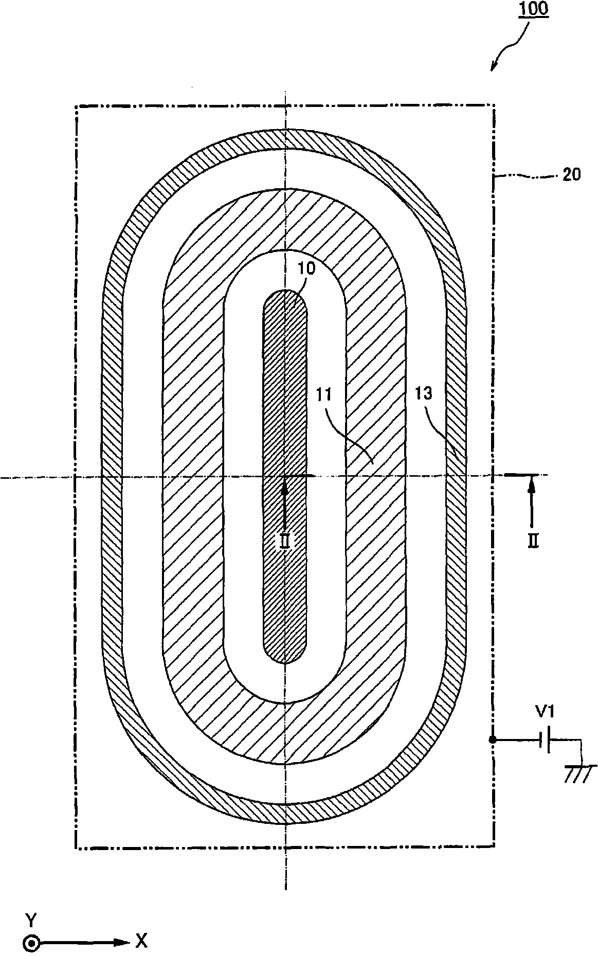
[0054] figure 1 It is a plan view of a cathode unit including a magnet member (magnetic field forming means) according to an embodiment of the present invention.

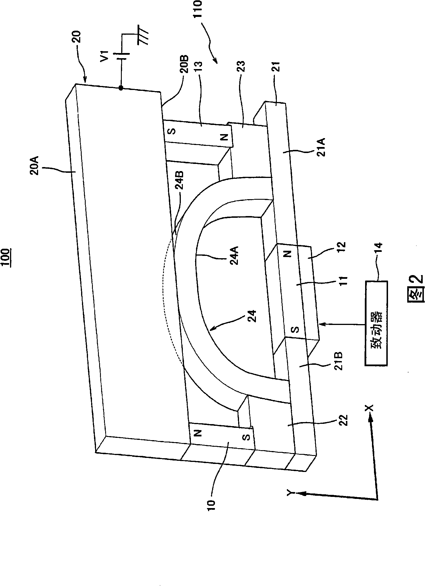
[0055] Also, Figure 2 is along the figure 1 Perspective view of the cathode unit of the portion of the II-II section line.

[0056] Also, in figure 1 In order to simplify the drawing, only the magnet section of the magnet member 110 is shown.

[0057] And for convenience, in figure 1 As in FIG. 2 (the same is true for FIG. 3 ), each component of the cathode unit 100 will be described with the width direction of the target 20 being the X direction and the thickness direction of the target 20 being the Y direction.

[0058] Moreover, the depth direction (direction perpendicular to the X direction and the Y direction) of each component of the magnet member 110 in FIG. Extended composition, in this case ...


PUM


Abstract

A magnet structure arranged to achieve wide erosion of a target by varying distribution of the line of magnetic force on the surface of the target by a simple drive mechanism. A magnet structure (110) comprises main magnets (10, 13) arranged on a rear surface (20B) side of a target (20) to form main line of magnetic force reaching a target front surface (20A), a correction magnet (11) arranged on the rear surface (20B) side of the target (20) to form correction line of magnetic force for varying distribution of flux density by the main line of magnetic force, magnetic paths (21A, 21B, 24) of correction line of magnetic force arranged on the rear surface (20B) side of the target (20), and magnetic field correction means (12, 14) which can alter the intensity of correction line of magnetic force penetrating the interior of the magnetic paths (21A, 21B, 24).

Description

technical field [0001] The present invention relates to a magnet member for a magnetron sputtering device, a cathode unit, and a magnetron sputtering device (hereinafter referred to as "magnet members, etc."). Improvement technology such as magnet components for controlled sputtering. Background technique [0002] A film formation method that utilizes the sputtering phenomenon by causing ions (such as Ar ions) to collide with a sputtering target material in a vacuum, causing atoms of the sputtering target to fly out and attaching the atoms to a substrate facing the sputtering target material has always been known. [0003] As a method of such a sputtering phenomenon, the magnetron sputtering film-forming method can form a channel-shaped leakage magnetic field larger than a specified magnetic flux density on the surface of the sputtering target (the surface opposite to the substrate), so it can be used The Lorentz force captures the secondary electrons generated during the ...

Claims


Application Information

Patent Timeline
Patent Type & Authority Applications(China)
IPC IPC(8): C23C14/35
CPCC23C14/3407H01J37/3405H01J37/3461C23C14/35H01J37/3452G11B7/26
Inventor 近藤隆彦堀崇展岩崎安邦米山信夫
Owner SHIN MEIWA IND CO LTD
Why Eureka
Try Eureka