Design method of tangential gradient thermal spraying coating for complex profile workpieces

a technology of complex profile workpieces and thermal spraying coatings, applied in coatings, design optimisation/simulation, instruments, etc., can solve the problems of high material cost and processing cost, complex spatial geometrical structure, and inability to meet homogeneous coating requirements, etc., to achieve effective prolonging service life and reducing the average erosion rate

Active Publication Date: 2019-11-28
SHANDONG UNIV
View PDF2 Cites 3 Cited by
  • Summary
  • Abstract
  • Description
  • Claims
  • Application Information

AI Technical Summary

Benefits of technology

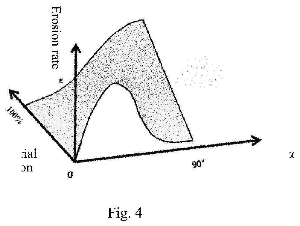
[0024]In the present invention, a coating with erosion-resistant performance matching the impact angle change can be designed on the complex profile surface, which solves the erosion-resistant problem of the complex profile that a homogeneous material coating cannot meet the high range of change of the impact angle.
[0025]For the complex profile part with the large range of change of the impact angle, the erosion of the tangential gradient coating obtained in the present invention is more uniform, and the overall average erosion rate is lower. The method can be used for strengthening of new products and size repair of damaged parts, and can effectively prolong the service life.

Problems solved by technology

A large centrifugal compressor impeller is a typical complex profile part, which is generally made of an ultra-high strength material, and is complex in the spatial geometrical structure and high in material cost and processing cost.
Blade thinning is an important damage form due to the erosion wear of gas-solid two-phase flow.
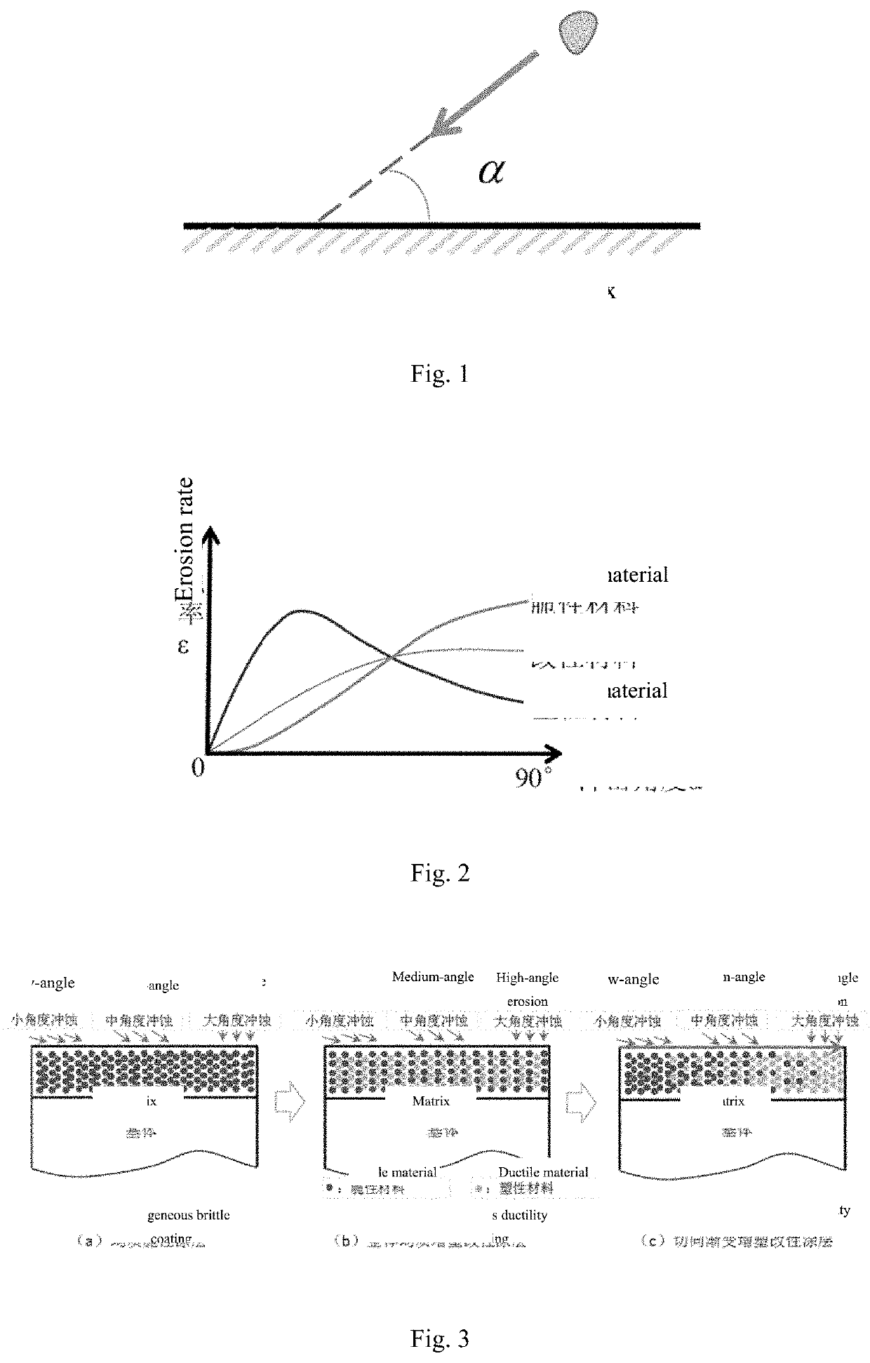
As shown in FIG. 3, the homogeneous coating cannot meet the requirement of erosion-resistant performance of the complex profile surface at various impact angles when it is impacted, as the change range of the impact angle on the whole profile is great.

Method used


Image

  • Design method of tangential gradient thermal spraying coating for complex profile workpieces
  • Design method of tangential gradient thermal spraying coating for complex profile workpieces

Examples


Embodiment Construction

[0031]It should be noted that the following detailed description is illustrative and intended to provide further description for the present application. Unless otherwise indicated, all technical and scientific terms used herein have the same meanings as commonly understood by those of ordinary skill in the art to which the present application pertains.

[0032]It needs to be noted that the terms used herein are only used for describing the embodiments, rather than being intended to limit the exemplary embodiments of the present invention. As used herein, unless otherwise indicated expressly in the context, singular forms are also intended to include plural forms. In addition, it should also be understood that the words “comprise” and / or “include” as used in the specification indicate the presence of features, steps, operations, devices, components and / or combinations thereof.

[0033]As introduced in the background art, strengthening or repairing the complex profile part by the homogeneo...


PUM

PropertyMeasurementUnit
impact angleaaaaaaaaaa
erosion-aaaaaaaaaa
erosion testaaaaaaaaaa

Abstract

A design method of tangential gradient thermal spraying coating for complex profile workpieces solves the erosion-resistant problem, and obtains a corresponding relation between the ductile-brittle ratio of the thermal sprayed coating and the impact angle change. The method includes: determining the complex profile part surface impact angle change rule according to the part operation environment conditions; selecting an erosion-resistant coating material according to the service condition requirement; obtaining the relation among the impact angle, ductile-brittle angle and erosion rate of the coating by an erosion test; determining the coating and the impact angle ductile-brittle corresponding relation curve; and performing spraying by using dual-channel powder feeding thermal spraying equipment the powder feeding quantity of which is adjustable in real time, based on a matching relation between the tangential gradient coating and the surface impact angle.

Description

FIELD OF THE INVENTION[0001]The present invention relates to the field of thermal spraying technology, in particular to a design method of tangential gradient thermal spraying coating for complex profile workpieces.BACKGROUND OF THE INVENTION[0002]Parts with complex profile in erosion conditions are widely applied to the industries of petroleum, chemical engineering, metallurgy and the like, and play an important role in economic development. A large centrifugal compressor impeller is a typical complex profile part, which is generally made of an ultra-high strength material, and is complex in the spatial geometrical structure and high in material cost and processing cost. Blade thinning is an important damage form due to the erosion wear of gas-solid two-phase flow. Thermal spraying technology is one of the important technologies for enhancing the erosion-resistant performance of the surface.[0003]The erosion rate, as an important indicator of erosion wear, is greatly influenced by ...

Claims


Application Information

Patent Timeline
Patent Type & Authority Applications(United States)
IPC IPC(8): C23C4/12G06F17/50
CPCG06F30/17G06F30/20C23C4/04C23C4/06C23C4/12C23C4/073G06F30/28G06F2111/04C23C4/10
Inventor LI, FANGYILU, HAIYANGLI, ZHENDU, JIYUSHANG, JIANTONGLI, JIANFENGWANG, LIMINGLI, YANLELIU, ZIWUZHANG, XINGYIRAN, XUEJU
Owner SHANDONG UNIV
Why Eureka
Try Eureka