Vehicle maintenance prompting system

A vehicle and system hardware technology, which is applied in vehicle maintenance, vehicle maintenance/repair, registration/instruction of vehicle operation, etc. It can solve problems such as delayed maintenance, early maintenance of vehicles, and dislocation of maintenance time and maintenance time, and achieves low price Effect

Inactive Publication Date: 2008-11-12
徐立
0 Cites 45 Cited by

AI-Extracted Technical Summary

Problems solved by technology

[0005] The invention discloses a vehicle maintenance reminding system, which solves the technical problem of the existing vehicle actual...

Abstract

The invention belongs to the technical field of vehicle maintenance and relates to a vehicle maintenance reminding system which includes a system hardware terminal that is arranged on the body of a vehicle and used for collecting parameter information relevant to the vehicle maintenance and storing the collected parameter information; a central information processing center which receives the parameter information relevant to the vehicle maintenance and stores the parameter information into a database, checks the change process of the received parameter information relevant to the vehicle maintenance, generates the information of the items and the dates of the vehicle maintenance and transmits the information by the Internet; and a system software terminal; the central information processing center transfers the information of the items and the dates of the vehicle maintenance generated by central information processing center to the system software terminal by the Internet and the system software terminal reminds a vehicle owner to carry out maintenance. The vehicle maintenance reminding system of the invention solves the existing technical problem that the actual maintenance time of the vehicle is misplaced with the time actually needed by the vehicle maintenance, namely, the forward maintenance or the hysteretic maintenance of the vehicle.

Application Domain

Technology Topic

System hardwareTTEthernet +6

Image

  • Vehicle maintenance prompting system
  • Vehicle maintenance prompting system
  • Vehicle maintenance prompting system

Examples

  • Experimental program(1)

Example Embodiment

[0036] The present invention will be described in detail below in conjunction with the accompanying drawings.
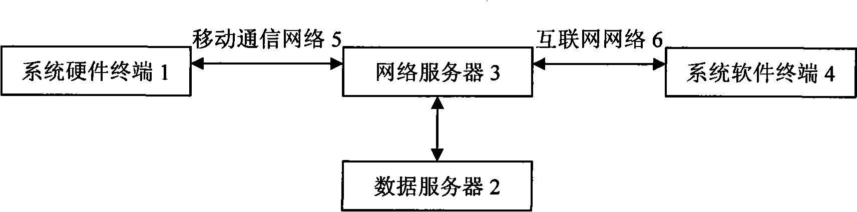
[0037] figure 1 The structure of the vehicle maintenance reminder system according to the present invention is shown, which includes: system hardware terminal 1; data server 2; network server 3; system software terminal 4; mobile communication network 5;
[0038] The system hardware terminal 1 has the ability to collect vehicle driving-related data and wireless communication capabilities, and is used to collect parameter information related to vehicle maintenance, store the collected parameter information related to vehicle maintenance, and send the collected parameter information through the mobile communication network 5 Parameter information related to vehicle maintenance.
[0039]The data service terminal 2 has a database for storing parameter information related to vehicle maintenance, receives the parameter information related to vehicle maintenance from the system hardware terminal 1, stores the parameter information related to vehicle maintenance, and checks the received information related to vehicle maintenance. The change process of the parameter information and refer to the maintenance parameters and maintenance items set correspondingly in the database to generate information related to the vehicle maintenance date and maintenance items; send the generated vehicle maintenance date and maintenance item information to the system software terminal 4 through the Internet.
[0040] The system software terminal 4 receives the information on the vehicle maintenance date and maintenance items generated above, queries the original relevant data of the vehicle stored in the data service terminal 2, and then collects and processes the vehicle information obtained according to the system hardware terminal 1 and data service terminal 2. According to the usage situation, make corresponding technical processing decisions, such as whether to increase the maintenance frequency of certain maintenance items between regular maintenance, and remind the car owner to send the vehicle to the maintenance department for maintenance and repair by phone, text message, email, etc.
[0041] figure 2 is to describe the system workflow:
[0042] According to the specific performance of the vehicle, the set maintenance cycle and maintenance items are entered in the data service terminal 2 in advance, and the system hardware terminal 1 collects parameter information related to vehicle maintenance within a fixed period that can be set, such as driving speed, driving The working status of electronic control components such as mileage, engine, gearbox, ABS (brake), engine oil sensor, etc., generate and store report messages related to vehicle maintenance parameter information, and send the report messages generated by mobile communication network 5 to Network server 3 and data server 2; The report message of the vehicle maintenance date and the information of maintenance item sent by Internet network 6 sends to system software terminal 4, carries out maintenance reminder to car owner by system software terminal 4, and can according to the usage situation of vehicle Inform the car owner whether the maintenance frequency of certain maintenance items needs to be increased between regular maintenance.
[0043] image 3 The structure of the system hardware terminal 1 of the present invention is shown, including: GPS module 11, mobile communication module 12, main program controller 13, data acquisition control module 14, power supply module 15, GPS receiving antenna 16, mobile communication antenna 17, printing System circuit board 18, casing 19.
[0044] The printed circuit board 18 is installed inside the casing 19 . GPS receiving antenna 16 is connected with GPS module 11, and GPS module 11 is connected with main program controller 13; Mobile communication antenna 17 is connected with mobile communication module 12; Mobile communication module 12 is connected with main program controller 13; Main program Controller 13 is connected with data acquisition control module 14; Power module 15 is connected with GPS module 11, mobile communication module 12, main program controller 13, data acquisition control module 14 respectively, provides working voltage for above-mentioned module; Above-mentioned module and GPS receiving antenna 16, mobile communication antenna 17 are all installed on the printed circuit board 18; Electronic Control Unit (ECU) is connected.
[0045] image 3 The mobile communication module 12 and the mobile communication antenna 17 are figure 1 In the mobile communication network 5, the wireless communication mode adopted by the mobile communication network 5 is the GPRS transmission mode of the GSM system.
[0046] Figure 4 It is the working flow chart of the system hardware terminal 1, and its working process is as follows:
[0047] In a fixed period that can be set, the mobile communication antenna 17 transmits the data collection control command sent from the system software terminal 5 to the mobile communication module 12, and the GPS receiving antenna 16 transmits the vehicle orientation information and orientation change information to the GPS module 11 After these two information are sent to the main program controller 13 to carry out the output control process, the control instruction is sent into the data acquisition control module 14, and the data acquisition control module 14 communicates with the vehicle interior electronic control unit (ECU) by the vehicle interior diagnosis protocol, and realizes Engine start or shutdown signal detection, engine control system detection, gearbox control system signal detection, oil pressure sensor signal detection, fuel sensor signal detection, vehicle speed sensor vehicle speed pulse signal detection, speed sensor speed pulse signal detection, acceleration sensor signal detection, Braking system control system signal detection, clutch control system signal detection and other operations, the detected information may include: real-time vehicle speed, mileage, engine oil pressure status, fuel usage status, engine operation changes, etc.; the information detected above Send back to the data acquisition control module 14 for processing, and after the main program controller 13 performs output control processing, the collected data is sent to the mobile communication module 12 and the mobile communication antenna 17 to send to the data service terminal 2 .
[0048] Figure 5 Show data service terminal 2 structure of the present invention:
[0049] The data service terminal 2 includes a data communication unit 21 ; a database 22 ; a central storage unit 23 ; and a data comparison unit 24 .
[0050] A data communication unit 21, configured to perform data communication with the system hardware terminal through a mobile communication network;
[0051] The database 22 stores parameter information related to vehicle maintenance and pre-sets the vehicle maintenance cycle and maintenance content according to the maintenance manual;
[0052] The central storage unit 23 includes an area for storing a control program controlling the overall operation of the data service terminal 2 and an area for temporarily storing data generated when the control program is executed.
[0053] The data comparison unit 24 checks the change process of the received parameter information related to vehicle maintenance, and refers to the database 22 to set the vehicle maintenance period and maintenance content according to the maintenance manual, and generates and sends information on the vehicle maintenance date and maintenance items ;
[0054] refer to Image 6 , the workflow of data service terminal 2:
[0055] The data communication unit 21 performs data communication with the system hardware terminal 1 through the mobile communication network 5 provided by the network server 3 .
[0056] The database 22 stores the parameter information related to vehicle maintenance and the vehicle maintenance manual to set the vehicle maintenance cycle and maintenance content. The parameter information related to vehicle maintenance can be real-time driving speed, mileage, engine oil pressure status, fuel consumption status, engine Changes in water temperature, etc.; the vehicle maintenance cycle and maintenance content set in the maintenance manual can be the original relevant data of the vehicle, such as: the vehicle manufacturer, the regular maintenance time and mileage specified by the original factory, the maintenance time and mileage of the running-in period specified by the original factory, and the vehicle has been driven Mileage, car owner maintenance habits, etc.
[0057] The central storage unit 23 includes an area for storing a control program that controls the overall operation of the data service terminal 2, and an area for temporarily storing data generated when the control program is executed.
[0058] The data comparison unit 24 controls the overall operation of the data service terminal 2, and upon receiving parameter information related to vehicle maintenance through the data communication unit 21, the data comparison unit 24 detects a change in information from the report information of the parameter information related to vehicle maintenance process and store the detected change information in the central storage unit 23. If the received parameter information related to vehicle maintenance is stored in the database 22, then the data comparison unit 24 compares and analyzes the detected change information stored in the central storage unit 23 and the parameter information related to vehicle maintenance in the database 22 to The search corresponds to setting the vehicle maintenance cycle and maintenance content according to the maintenance manual. When the corresponding maintenance cycle and maintenance content are found, the data comparison unit 24 generates information to determine the vehicle maintenance date and maintenance items, and through the network server 3, the vehicle will be determined. The information of the maintenance date and maintenance items is sent to the system software terminal 5 .
[0059] The network server 3 is used to provide wireless network services for the system hardware terminal 1 to communicate with the data service terminal 2 and the system software terminal 4, and to provide the data service terminal 2 with an Internet network for data communication with the system software terminal 4.
[0060] Here, the function of the network server 3 can be realized in many ways, and the Internet network 6 can adopt the Internet.
[0061] The system structure of system software terminal 4 has many ways to realize, only refer to here Figure 7 Describe its workflow:
[0062] The system software terminal 4 automatically sends control instructions to the system hardware terminal 1 through the mobile communication network 5 within a fixed period that can be set; the system hardware terminal 1 collects data related to vehicle maintenance and then transmits the data through the mobile communication network 5 to Data service terminal 2; data service terminal 2 compares the database setting parameters to process the collected data, and data service terminal 2 sends the report message of the vehicle maintenance date and maintenance item information generated after processing to the system software through the Internet network 5 Terminal 4, the system software terminal 4 receives the information of the vehicle maintenance date and maintenance items generated above, and queries the original relevant data of the vehicle stored in the data service terminal 2, and then collects and processes it according to the system hardware terminal 1 and data service terminal 2. Based on the actual vehicle usage, decide whether to increase the maintenance frequency of some maintenance items between regular maintenance, and remind the owner to send the vehicle to the maintenance department for maintenance and repair by phone, text message, email, etc.
[0063] Explanation of related technical terms:
[0064] ECU: The electronic control unit is the core control element of the electronically controlled fuel injection system. ECU is actually a microcomputer. On the one hand, it receives signals from sensors, on the other hand, it completes the processing of these information, and sends out corresponding control instructions to control the correct actions of actuators. In this way, engine performance, fuel consumption and Exhaust emissions are kept at their best. In addition, the electronic control unit also has the function of automatically cutting off the electric gasoline pump circuit. For example, the deceleration fuel cut-off control means that when the vehicle suddenly releases the accelerator pedal to decelerate during high-speed driving (forced idling condition), the computer automatically cuts off the fuel. Injection until the engine speed drops to the set low speed and then resume fuel injection. Its purpose is to control the emission of harmful substances during rapid deceleration, reduce fuel consumption, and prompt the engine speed to drop as soon as possible, which is conducive to vehicle deceleration. After the cold car is started, if the engine is not warmed up before the vehicle is driven, the electronic control unit also has the function of limiting the rapid increase of the speed to prevent excessive wear of the engine cylinder when the car is cold.
[0065] OBD: 0n-Board Diagnostics, an on-board computer diagnostic system, vehicle maintenance personnel can use this equipment to perform fault diagnosis on all vehicles produced according to the standard through the same diagnostic interface at the same location.
[0066] ABS: Anti-lock braking system is a vehicle safety control system with the advantages of anti-skid and anti-lock. ABS is an improved technology based on conventional braking devices, which can be divided into two types: mechanical and electronic.

PUM

no PUM

Description & Claims & Application Information

We can also present the details of the Description, Claims and Application information to help users get a comprehensive understanding of the technical details of the patent, such as background art, summary of invention, brief description of drawings, description of embodiments, and other original content. On the other hand, users can also determine the specific scope of protection of the technology through the list of claims; as well as understand the changes in the life cycle of the technology with the presentation of the patent timeline. Login to view more.

Similar technology patents

Classification and recommendation of technical efficacy words

Why Eureka
Try Eureka