Packet transmission control method and apparatus

A technology of packet transmission and control method, which is applied in the direction of transmission system, selection device, digital transmission system, etc., can solve problems such as delay jitter, achieve the effect of eliminating jitter, simple method mechanism, and alleviating QoS problems

Inactive Publication Date: 2008-11-12
HUAWEI TECH CO LTD
View PDF0 Cites 34 Cited by
  • Summary
  • Abstract
  • Description
  • Claims
  • Application Information

AI Technical Summary

Problems solved by technology

[0008] The embodiment of the present invention provides a packet transmission control method and device, which solves the problem of the transmission delay caused by network packet transmission after the Abis interface used for communication in the wireless communication network is IP-based and the TRAU frame is transmitted in packets. Delay jitter caused by

Method used


Image

  • Packet transmission control method and apparatus
  • Packet transmission control method and apparatus
  • Packet transmission control method and apparatus

Examples


Embodiment 1

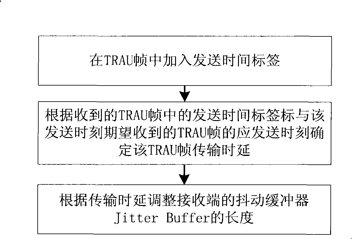
[0032] This embodiment provides a packet transmission control method, which can be used to prevent packet jitter of TRAU frame packet transmission, and can eliminate the jitter and disorder generated by the TRAU frame after packet transmission, especially eliminate the jitter and disorder caused by the transmitted voice. influence, such as figure 1 shown, including:

[0033] In the TRAU frame of the transcoding rate adaptation unit for packet transmission, add a sending time tag marking the sending moment of the TRAU frame;

[0034] Determine the transmission time delay of the TRAU frame according to the sending moment of the sending time tag mark in the received TRAU frame and the sending moment of the TRAU frame expected to be received at the sending moment;

[0035]The length of the Jitter Buffer at the receiving end is adjusted according to the transmission delay, so that the adjusted length of the Jitter Buffer is adapted to the transmission delay, and the jitter caused ...

Embodiment 2

[0096] This embodiment provides a packet transmission control device, which can be used to implement the jitter-proof packet transmission control method described in Embodiment 1. The device is as follows Figure 4 As shown, it can be used at the receiving end, including:

[0097] The tag processing module is used to process the sending time tag in the received TRAU frame, and obtain the sending time of the TRAU frame from the sending time tag;

[0098] The transmission delay determination module is used to determine the transmission delay according to the sending time of the TRAU frame obtained by the label processing module and the sending time of the frame expected to be received at the sending time;

[0099] A jitter buffer adjustment module, configured to adjust the length of the jitter buffer Jitter Buffer at the receiving end according to the transmission delay determined by the transmission delay determination module, so that the adjusted length of the jitter buffer Ji...

Embodiment 3

[0107] This embodiment provides another packet transmission control device, which can be used in the anti-jitter and out-of-sequence packet transmission control method of Embodiment 1. The device is as follows: Figure 8 As shown, it can be used at the sending end, including:

[0108] A tag adding module is used to add a sending time tag marking the sending time of the frame to the TRAU frame sent by the transcoding rate adaptation unit TRAU;

[0109] The code conversion rate adaptation unit TRAU frame group frame sending unit is used to send the TRAU frame after the tag adding module adds the sending time tag and the frame sequence number tag.

[0110] In summary, in the embodiment of the present invention, the JitterBuffer is established by the receiver BTS in the GSM network to eliminate the transmission jitter and disorder of the TRAU frame in the network transmission, effectively alleviating the problems caused by the GSM packetization (IPization) transmission. The QoS p...


PUM


Abstract

The invention relates to a grouping transmission control method and a device thereof. The method includes: adding transmitting time labels to a Transcoding Rate Adapter Unit TRAU frame; ensuring the propagation delay time of the TRAU according to the received transmitting time labels in the TRAU frame and the expected transmitting time of the TRAU frame expectedly received by the transmitting time; adjusting the length of a Jitter Buffer at the receiving terminal according to the propagation delay time of the TRAU frame. By establishing the Jitter Buffer at the receiving terminal of the TRAU frame, the method is dynamically adjusted according to the network transmission conditions, thereby eliminating the transmission jitter and disorder and effectively relieving the problem of QoS (Quality of Service) due to GSM (Global System Mobile) network packetization transmission.

Description

technical field [0001] The invention relates to a communication control technology, in particular to a method and device for controlling packet transmission during communication in a communication network. Background technique [0002] Global System for Mobile Communications (GSM, Global System for Mobile communications) is the mobile communication network with the widest coverage and the largest number of users in the world. The GSM network is mainly divided into core network and access network on the network side. Since the birth of the GSM network, it mainly adopts Time Division Multiplexing (TDM, TimeDivision Multiplex) mode for transmission. In recent years, with the development of network technology and wireless communication technology, the core network of the GSM network has gradually transitioned to the softswitch based on the 2G / 3G common platform, and the access network is also moving towards the direction of IP. [0003] The main network elements on the access ...

Claims


Application Information

Patent Timeline
Patent Type & Authority Applications(China)
IPC IPC(8): H04Q7/22H04L12/56H04W28/02
Inventor 贾翔宇郭江
Owner HUAWEI TECH CO LTD
Why Eureka
Try Eureka