Pneumatic belt tire

A technology for radial tires and tires, which is applied to the reinforcement layer of pneumatic tires, tire parts, tire treads/tread patterns, etc. To avoid layer bending and other problems, achieve the effect of maintaining cost competitiveness and improving partial wear performance

A technology for radial tires and tires, which is applied to the reinforcement layer of pneumatic tires, tire parts, tire treads/tread patterns, etc. To avoid layer bending and other problems, achieve the effect of maintaining cost competitiveness and improving partial wear performance

CN101306631AInactive Publication Date: 2008-11-19BRIDGESTONE CORP

Image

  • Pneumatic belt tire
  • Pneumatic belt tire
  • Pneumatic belt tire

Examples


Embodiment 1

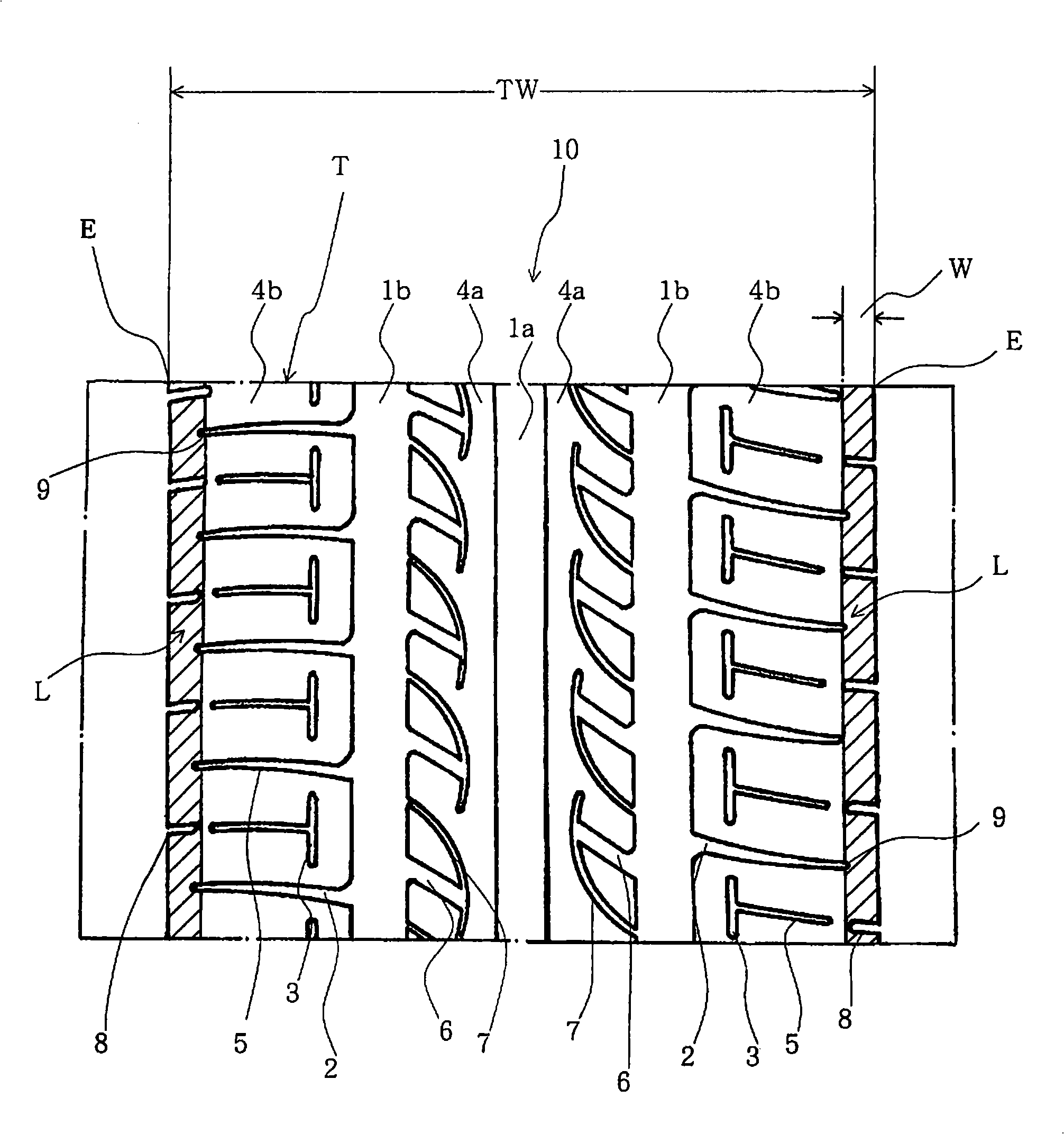
[0039] has been trial-produced with figure 1 A tire with the tread pattern shown and a 2-steel belt structure that satisfies the following conditions.

[0040] Tire size specification: 155 / 65R13 73S

[0041] Tread width TW: 120mm

[0042] The ratio of pattern groove to pattern block area (negative rate): 32%

[0043] Width of circumferential main groove 1a: 18mm, width of 1b: 9.1mm

[0044] Depth of circumferential main grooves 1a, 1b: 6.0mm

[0045] The width of the part of the transverse groove 2 connected with the circumferential main groove 1b: 2.5 ~ 4.5mm (varies with the pitch)

[0046] Depth of transverse groove 2: 5mm

[0047] Width w of the ground portion L: 5mm

[0048] Width of intermittent slit auxiliary groove 3: 1.5mm

[0049] Depth of intermittent gap auxiliary groove 3: 5mm

[0050] Radius of curvature R1: 1000mm

[0051] Radius of curvature R2: 5mm

[0052] Conventional Example 1

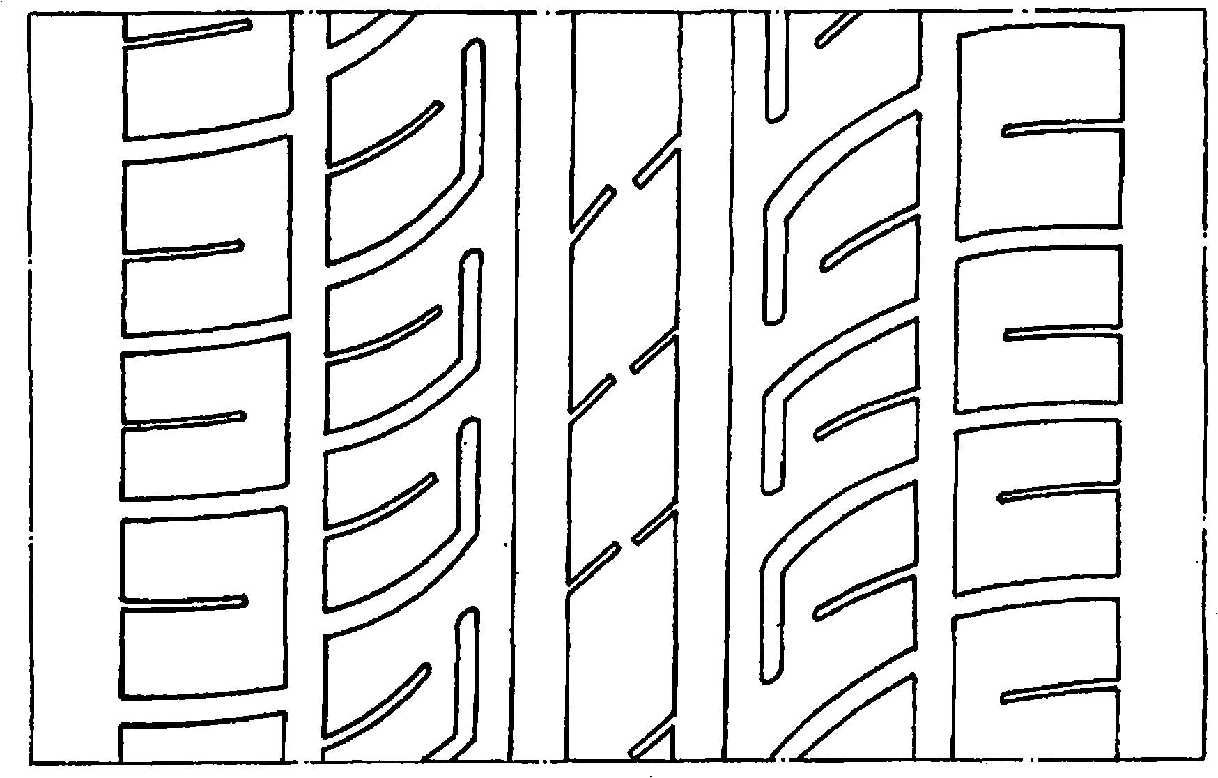
[0053] use has image 3 A known tire having the tread pattern and...

Embodiment 2

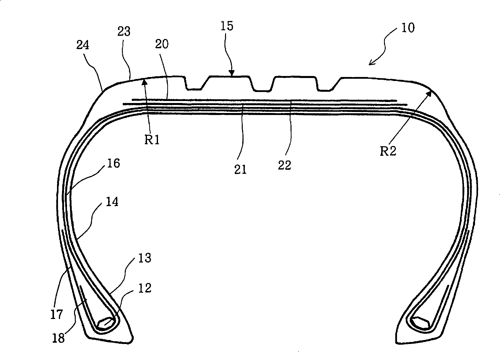
[0070] Trial out: In addition to having Figure 4 A tire having one belt reinforcement layer in addition to the tread pattern and two-wire belt structure shown, and satisfying the following conditions.

[0071] Tire size specification: 195 / 65R15 91H

[0072] Tread width TW: 140mm

[0073] Groove to block area ratio: 34%

[0074] Width of circumferential main groove 1a: 9mm, width of 1b: 10.5mm

[0075] Depth of circumferential main grooves 1a, 1b: 7.5mm

[0076] Width of the portion of the transverse groove 2 communicating with the circumferential main groove 1b: 2.5 to 4.5 mm (varies with the pitch)

[0077] Depth of transverse groove 2: 5mm

[0078] Width w of the ground portion L: 5mm

[0079] Width of intermittent slit auxiliary groove 3: 2mm

[0080] Depth of intermittent slit auxiliary groove 3: 6mm

[0081] Radius of curvature R1: 145mm

[0082] Radius of curvature R2: 36mm

[0083] Conventional example 2

[0084] Adopted in previous example 2: with Figur...


PUM


Abstract

The invention provides a pneumatic radial tire having cost competition and improving the bias abrasion performance to the tire shoulder by seeking for the optimization of the ground shape and the ground pressure. The pneumatic radial tire has a translot (2) having a plurality of circumferential main slots (1a, 1b) at the tread portion of the tire and extending along the width direction of the tire and a tread pattern for forming a plurality of ground lines (4a, 4b). In the tier shoulder ground line (4b) comprising ground end (E), a translot (2) extending from the circumferential main slots (1b) nearest to the ground end to the ground end (E) is stopped near the ground end, and continuous ground portions (L) are formed near the ground end. Side of the main slots (1b) of the tier shoulder ground line (4b) is approximately parallel to the intermittent slit auxiliary slot (3).

Description

technical field [0001] The present invention relates to a pneumatic radial tire. Specifically, it relates to a pneumatic radial tire which is cost-competitive and which improves partial wear performance of tire shoulders by optimizing the contact shape and contact pressure distribution. Background technique [0002] Conventionally, it is known in pneumatic tires that, for example, as described in Patent Document 1, by arranging a belt reinforcing layer between the belt layer and the tread, it is possible to suppress the centrifugal force during high-speed running from causing the tire to rotate. The tread portion produces a large radially increasing deformation toward the outside in the radial direction, and therefore, it is generally possible to reduce heat generation and deformation at the belt end, improve high-speed durability, and improve steering stability. [0003] However, the following tires are still widely used today because they do not have a belt reinforcement l...

Claims


Application Information

Patent Timeline
19 Nov 2008
Publication
CN101306631A
IPC
B60C11/03; B60C9/18; B60C9/28; B60C9/16
CPC
B60C9/0064; B60C9/1807; B60C9/1821; B60C11/01; B60C11/03; B60C11/0304; B60C11/0332; B60C2009/2012
Inventors
富田达也; 原田备弘