
Folding and unfolding mechanism of back-unfolding stabilizing fin device

A technology of retractable mechanism and fin stabilizer, which is applied in the direction of using hydrofoils to act on the surrounding water surface to reduce the movement of ships, etc. It can solve the problems of negative influence of fin function and large starting resistance of mechanism oil cylinder, etc., so as to change labor-intensive and time-consuming operations, extend The effect of service life and improvement of load-carrying conditions

Active Publication Date: 2008-11-19
SHANGHAI HUNTER MARINE EQUIP CO LTD
View PDF0 Cites 5 Cited by
  • Summary
  • Abstract
  • Description
  • Claims
  • Application Information

AI Technical Summary

Problems solved by technology

[0003] The key component of the rear-retractable fin stabilizer is its retractable mechanism. The existing technical scheme of this mechanism includes a retractable oil cylinder, a fin box, a sliding sleeve, a retractable connecting rod, a guide sleeve, a rotating body and a lock. The retractable oil cylinder is set in the guide sleeve, and the sliding sleeve can move axially on the guide sleeve. The retractable oil cylinder and the guide sleeve are fixed on the fin box and welded with the hull plate. A "self-locking angle" is set for the included angle between the center line of the retractable connecting rod and the released fin axis. This self-locking angle makes the axial force acting on the sliding sleeve smaller than the friction force generated by the radial force. The sliding sleeve It can be self-locking, so that the fins can be kept at the working position; the friction value established by the above-mentioned self-locking angle is affected by many factors. When the locking angle is large, the opposite is true. Most of the existing retractable fin stabilizer devices take a value of 5° left or right. The fin box vertical plate, therefore, the minimum self-locking angle of the existing structure, that is, the angle between the center line of the retractable connecting rod and the released fin axis after the baffle and the sliding sleeve are in contact is a "fixed value", which cannot adapt to Under the influence of many factors, the device can select a better minimum self-locking angle, which will have a negative impact on the function of the fins. In addition, there are technical problems that need to be improved in terms of use, maintenance and craftsmanship in the existing structure.

Method used


Image

  • Folding and unfolding mechanism of back-unfolding stabilizing fin device
  • Folding and unfolding mechanism of back-unfolding stabilizing fin device
  • Folding and unfolding mechanism of back-unfolding stabilizing fin device

Examples


Embodiment Construction

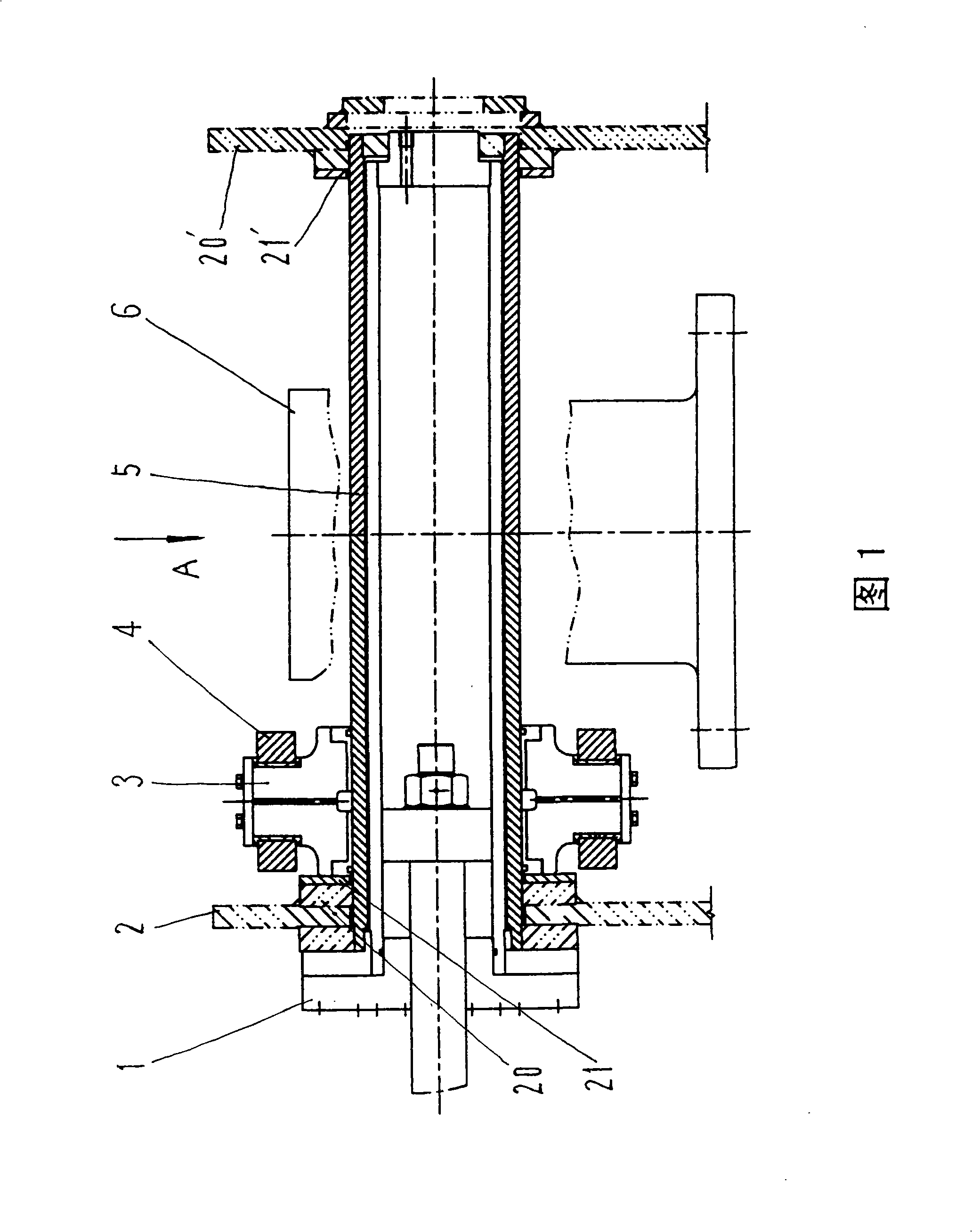
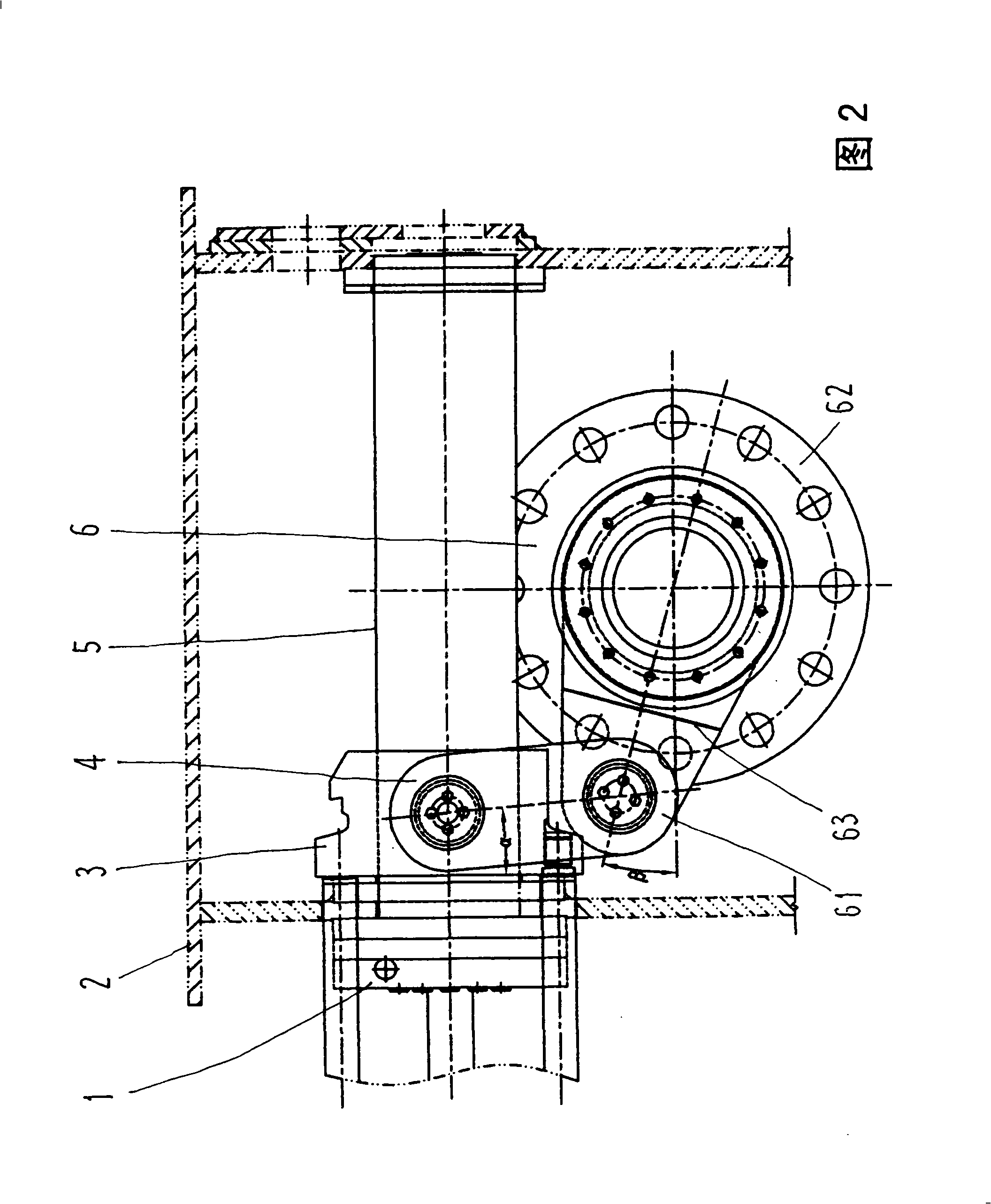
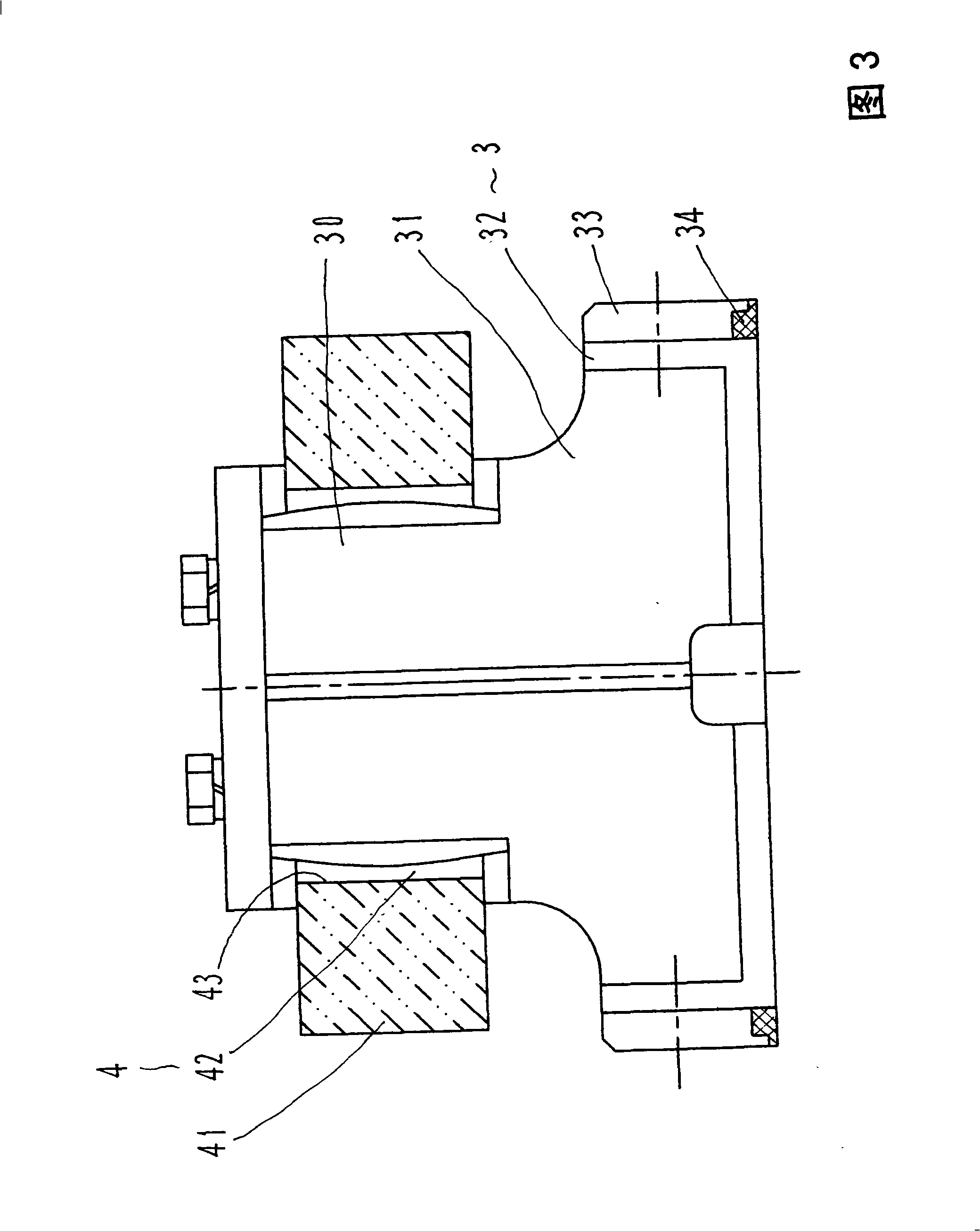
[0013] Referring to Figures 1 and 2, the retractable mechanism of the rear retractable fin stabilizer includes a retractable oil cylinder 1, a fin box 2, a sliding sleeve 3, a retractable connecting rod 4, a guide sleeve 5, a rotating body 6 and a locking mechanism.

[0014] The retractable oil cylinder 1 is installed on the front and rear vertical plates of the fin box 2 to drive the movement of the retractable mechanism. The piston rod of the retractable oil cylinder 1 is connected with the sliding sleeve 3 through two push-pull rods, and the retractable oil cylinder 1 is set on the guide sleeve. within 5.

[0015] The fin box 2 is the supporting member of the retractable mechanism. The box body of the fin box 2 and the front and rear vertical plates 20, 20 ′ are welded together with the hull plate to form a closed structure. The front and rear vertical plates 20, 20 Between ', the fixed guide sleeve 5 is stretched, and the insides of the front and rear vertical plates 20, 2...


PUM


Abstract

A back-retraction fin stabilizer retracting and extending mechanism is mainly used for solving the technical problems of anti-rolling performance improvement. The back-retraction fin stabilizer retracting and extending mechanism is characterized in that an adjusting plate with an adjustable thickness is assembled on a front vertical plate of a fin box; the adjusting plate is correspondingly sleeved on one end of a guide sleeve and is in contact with one end of a slide sleeve in the working position of the fin; another adjusting plate with an adjustable thickness is assembled on the rear vertical plate of the fin box on the other end of the guide sleeve and is in contact with the other end of the slide sleeve in the fin retracting position; and a radical spherical plain bearing is arranged on a retracting and extending connection rod; a rotating arm has a combination structure; and a split-type dustproof ring is adopted. The back-retraction fin stabilizer retracting and extending mechanism is suitable for various back-retraction fin stabilizers.

Description

Technical field: [0001] The present invention relates to an apparatus for reducing roll of a vessel, and more particularly to an apparatus for reducing the motion of the vessel using hydrofoil action on the surrounding water. Background technique: [0002] When a ship is navigating in the ocean, it will produce rolling motion under the action of wind and waves. The rolling of the ship will reduce the seaworthiness, damage the hull structure, affect the normal operation of equipment and instruments, and cause the cargo to shift or be damaged by impact. Passengers and crew members are dizzy, severe rolling may also cause danger, and may affect or even lose combat effectiveness on combat ships. In order to reduce ship rolling, the industry adopts various methods, such as bilge keels, anti-rolling water tanks, anti-rolling gyro, anti-rolling Anti-rolling equipment such as heavy hammers and fin stabilizers; with the advancement of technology and the increasing number of high-spee...

Claims


Application Information

Patent Timeline
IPC IPC(8): B63B39/06
Inventor 牛远振曾启盛黎汉荣徐安昌
Owner SHANGHAI HUNTER MARINE EQUIP CO LTD
Learn More