Charging protection circuit for battery

A protection circuit and battery charging technology, applied in the direction of battery overvoltage protection, battery disconnection circuit, safety/protection circuit, etc., can solve the problems of battery damage, battery chip out of control, easily damaged battery, etc., to prevent overvoltage charging Effect

Inactive Publication Date: 2008-11-19
HONG FU JIN PRECISION IND (SHENZHEN) CO LTD +1
View PDF0 Cites 14 Cited by
  • Summary
  • Abstract
  • Description
  • Claims
  • Application Information

AI Technical Summary

Problems solved by technology

Since the rechargeable battery is a capacitive load, there are strict restrictions on the charging voltage of the charger, but the existing chargers have no strict requirements on the charging voltage, and there is no corresponding overvoltage protection circuit
If the user accidentally uses a charging voltage higher than the standard voltage to charge the battery, the charging control chip of the battery may be out of control, causing unpredictable hidden dangers. For example, the temperature of some field effect tube components rises rapidly, causing the battery Smoke and fire, more serious may cause the battery to explode, not only damage the battery but also may cause a fire
[0003] In addition, some existing chargers are designed with two-pin plugs, but there is no fool-proof design. If the two-pin plugs are inserted incorrectly, the charging polarity will be just opposite. If the battery is charged directly, the battery will be easily damaged.

Method used


Image

  • Charging protection circuit for battery

Examples


Embodiment Construction

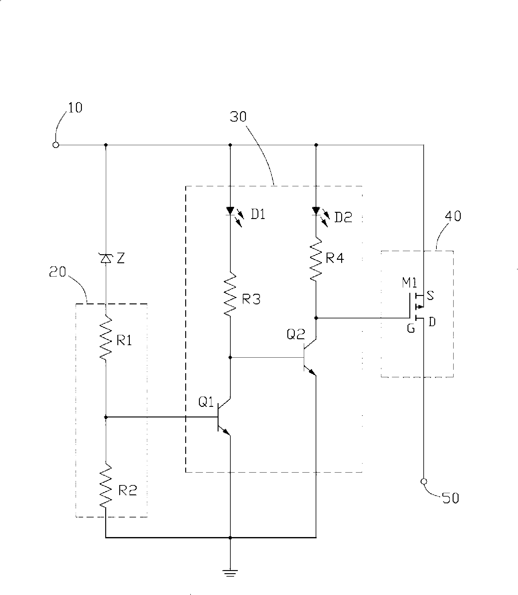
[0009] Please refer to figure 1 A preferred embodiment of the battery charging protection circuit of the present invention is set in a charger (not shown in the figure), and the battery charging protection circuit includes a charging power supply input terminal 10, a Zener diode Z, a voltage dividing device 20, A driving device 30 , a switching device 40 and a charging power output terminal 50 .

[0010] The charging power input terminal 10 is connected to the cathode of the voltage stabilizing diode Z, and the anode of the voltage stabilizing diode Z is grounded through the voltage dividing device 20 . The driving device 30 includes an input end and an output end, and the switching device 40 includes a control end, an input end and an output end. The output terminal of the voltage divider 20 is connected to the input terminal of the driving device 30, the output terminal of the driving device 30 is connected to the control terminal of the switching device 40, and the chargin...


PUM


Abstract

Disclosed is a battery charge protection circuit which includes a charge power supply input end, a zener diode, a voltage divider, a driving device, a switch device and a charge power supply output end. The charge power supply input end is connected with the negative pole of the zener diode whose positive pole is grounded through the voltage divider. The charge power supply output end provides a charge voltage; the voltage value of the zener diode is a standard charge voltage; when the charge voltage at the charge power supply output end exceeds the voltage value of the zener diode, the driving device outputs a control signal to switch off the witch device, so that the charge voltage at the charge power supply output end is shut off; thereby the charge power supply output end has no charge voltage, the charger stops charging the battery and prevents the battery from being damaged by over voltage charging.

Description

technical field [0001] The invention relates to a protection circuit, in particular to a battery charging protection circuit. Background technique [0002] At present, in addition to the charging function, most chargers also have certain protection functions, such as overcharging and short circuit protection functions for the battery. Since the rechargeable battery is a capacitive load, there is a strict limit on the charging voltage of the charger, but there is no strict requirement on the charging voltage in the existing chargers, and there is no corresponding overvoltage protection circuit. If the user accidentally uses a charging voltage higher than the standard voltage to charge the battery, the charging control chip of the battery may be out of control, causing unpredictable hidden dangers. For example, the temperature of some field effect tube components rises rapidly, causing the battery Smoke and fire, more serious may also cause the battery to explode, not only da...

Claims


Application Information

Patent Timeline
Patent Type & Authority Applications(China)
IPC IPC(8): H02H7/18
CPCH02J7/0031H02J7/00308
Inventor 陈樱熊金良
Owner HONG FU JIN PRECISION IND (SHENZHEN) CO LTD
Why Eureka
Try Eureka