Gas valve of tubular solenoid

A solenoid and gas technology, applied in the direction of electromagnets, valve details, valve devices, etc., can solve the problem of increasing the solenoid group and achieve the effect of avoiding missing

Inactive Publication Date: 2008-11-19
王嘉屏 +2
View PDF1 Cites 3 Cited by
  • Summary
  • Abstract
  • Description
  • Claims
  • Application Information

AI Technical Summary

Problems solved by technology

And increasing the number of turns of the electric turns will ...

Method used


Image

  • Gas valve of tubular solenoid
  • Gas valve of tubular solenoid
  • Gas valve of tubular solenoid

Examples


Embodiment Construction

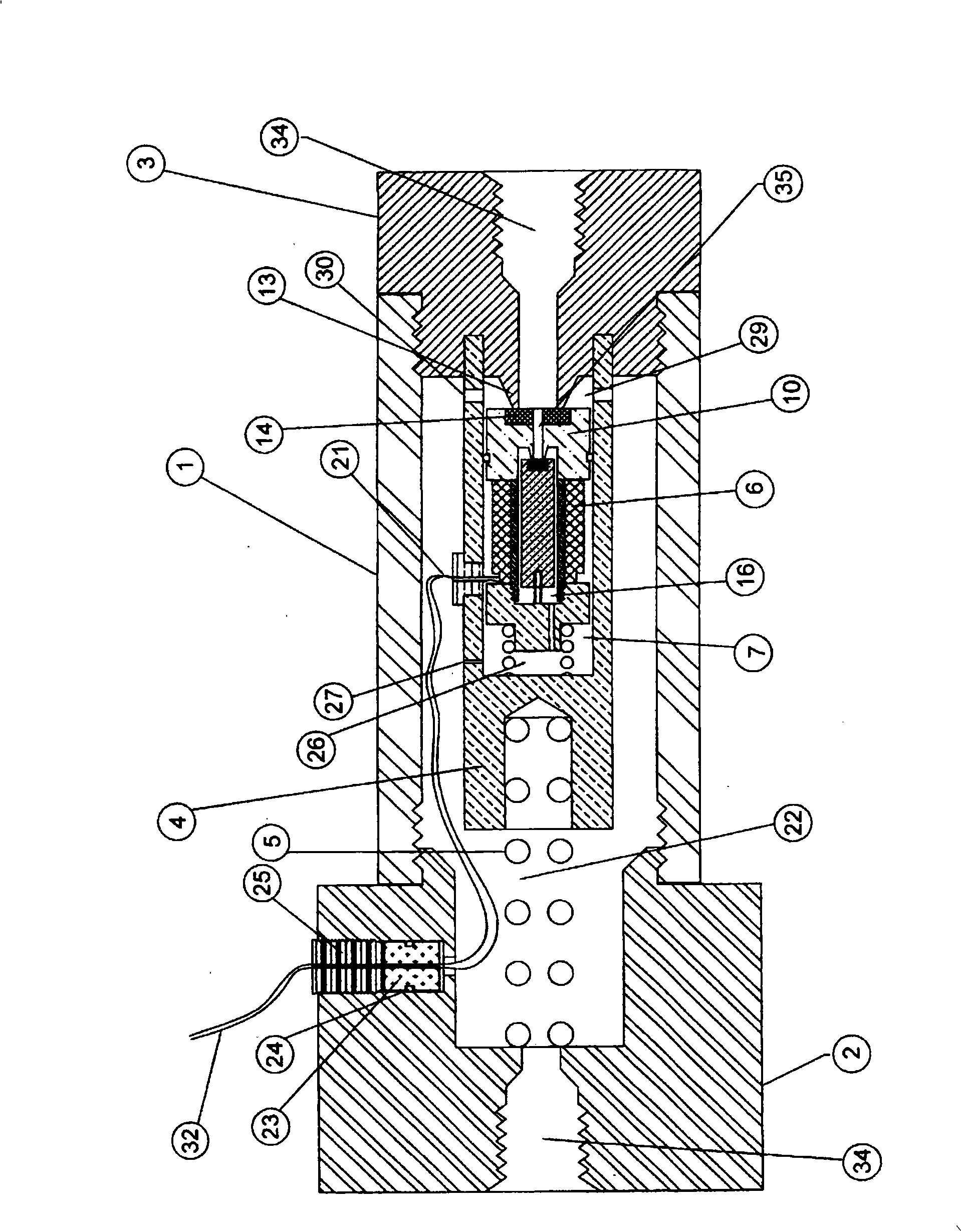
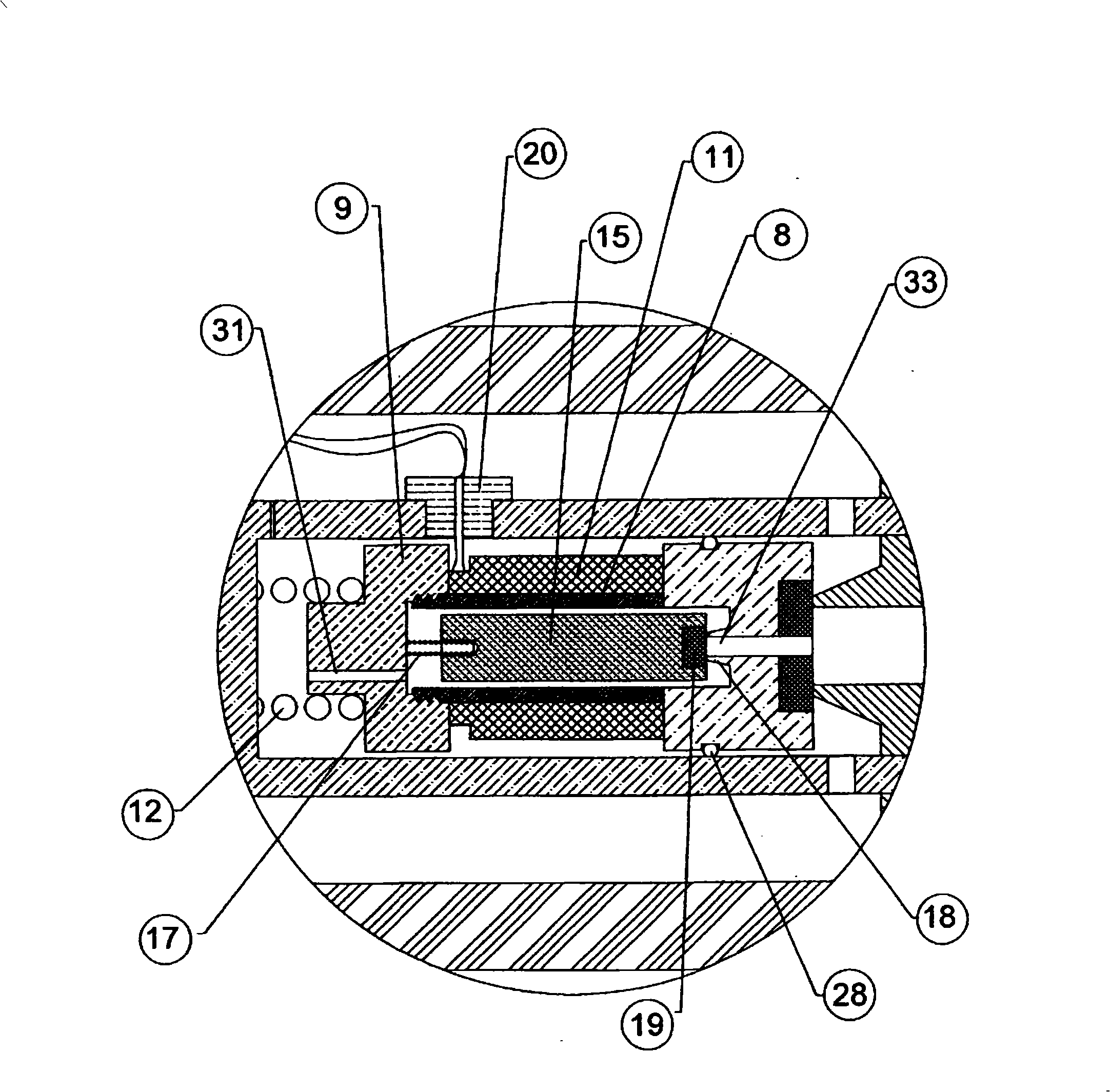
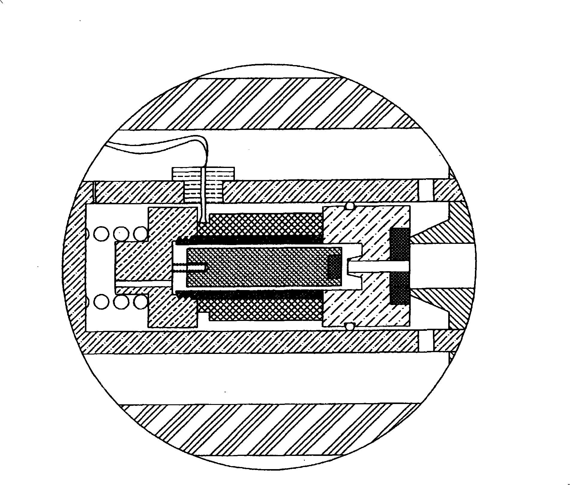
[0023] focus first on figure 1 with figure 2 , which shows a cross-section of a solenoid-in-tube gas valve. The valve tube 1 has a hollow hole with leads at both ends, which can be connected to the inlet configuration 2 and the outlet configuration 3 . Both configurations have corresponding configurations of the central bore 34 with internal leads for connection to the piping system. A supporting cylindrical body 4, pushed towards the aforementioned outlet arrangement 3 by a compression spring 5, has a cavity 7, providing space for the solenoid assembly 6 to move, which includes a hollow bush 8, a baffle 9, a flange 10 and an electrical turn 11.

[0024] In the "sealed" state, a compression spring 12 pushes the aforementioned solenoid assembly 6 towards the sealing seat 13 of the aforementioned outlet arrangement 3 . A plastic insert 14 is molded onto the aforementioned flange 10 to provide a sealing point. When a compression spring 17 pushes the electromagnetic rod 15 t...


PUM


Abstract

A solenoid gas valve having a solenoid assembly and inlet 2 and outlet 3 fittings is installed inside a tube. The opening and closing of the valve is operated by the pressure difference with an aid of the magnetic field. A compression spring 5 is attached to the support cylindrical body 4 and held against the inlet end fitting 2 while a moving solenoid assembly 6 is located inside the support cylindrical body 4. The moving solenoid assembly 6 that consists of a stop 9, a flange 10, a sleeve 8 and an electrical coil 11, is held by a second compression spring 12 that is attached to the inside of the support cylindrical body 4. A small moving magnetic rod 15 slides inside the sleeve 8 of the solenoid assembly 6. Acted by a third compression spring 17, the magnetic rod 15 seals the gas outlet through the bleed orifice 33 on the flange 10 of the solenoid assembly 6.

Description

Background of the invention [0001] This application is incorporated by reference for the entire disclosure of US Patent Application No. 10 / 924,789 including specification, drawings and abstract. [0002] The piping system setup for alternative fuel vehicles is complex, either natural gas or hydrogen, usually stored in a high pressure vessel and operated by solenoid gas valves. Generally, space within a vehicle is limited; thus a small valve and piping system is required. Additionally, an in-line inlet and outlet will simplify the layout of the ductwork. [0003] Valves are used to control the flow rate of fuel at a specific inlet pressure. Designing a suitable valve for all piping system requirements is difficult because of inlet pressure limitations and temperature variations. Properly sized threads can typically provide a pulling force that is only about one percent of the force necessary to displace a valve that is forced shut by high pressure gas. To overcome this, mos...

Claims


Application Information

Patent Timeline
IPC IPC(8): F16K31/06F16K27/02
CPCF16K31/0655F16K27/029F16K31/408H01F7/16
Inventor 王维庆王嘉屏
Owner 王嘉屏
Why Eureka
Try Eureka