Drilling tool

A technology for drilling tools and tools, which is applied to drilling accessories, manufacturing tools, drilling/drilling equipment, etc. It can solve problems such as processing troubles, failure to obtain broken life, troublesome inspections, etc., and achieve simple shapes and difficult Effects of breakage, ease of manufacture and inspection

Inactive Publication Date: 2008-12-03
UNION TOOL
View PDF1 Cites 10 Cited by
  • Summary
  • Abstract
  • Description
  • Claims
  • Application Information

AI Technical Summary

Problems solved by technology

[0005] For example, sometimes a very small diameter drill with a tool diameter of about 0.05 mm is used, but the possibility of breakage is high due to the extremely small rigidity of the tool, and the tool needs to be replaced frequently, or the PCB needs to be laminated and processed at the same time. Countermeasures such as reducing the number of processing times
[0006] In addition, in the visual inspection of the shape of the drill point, it is necessary to measure whether the left and right are balanced (the deflection of the cutting edge and the eccentricity of the chisel edge) to judge whether it is acceptable, but if the diameter becomes smaller, not only processing is troublesome, but also this inspection becomes troublesome.
[0007] Therefore, the current situation is that, for example, in Patent Document 1, although a predetermined structure of a single-blade drill that can ensure rigidity is disclosed even if the tool diameter is small, sufficient breakage life cannot be obtained.
In addition, since there are multiple drill point faces, the pass / fail inspection is troublesome as in the past

Method used


Image

  • Drilling tool
  • Drilling tool
  • Drilling tool

Examples


Embodiment Construction

[0035] The action of the present invention is shown based on the drawings, and preferred embodiments of the present invention are briefly described.

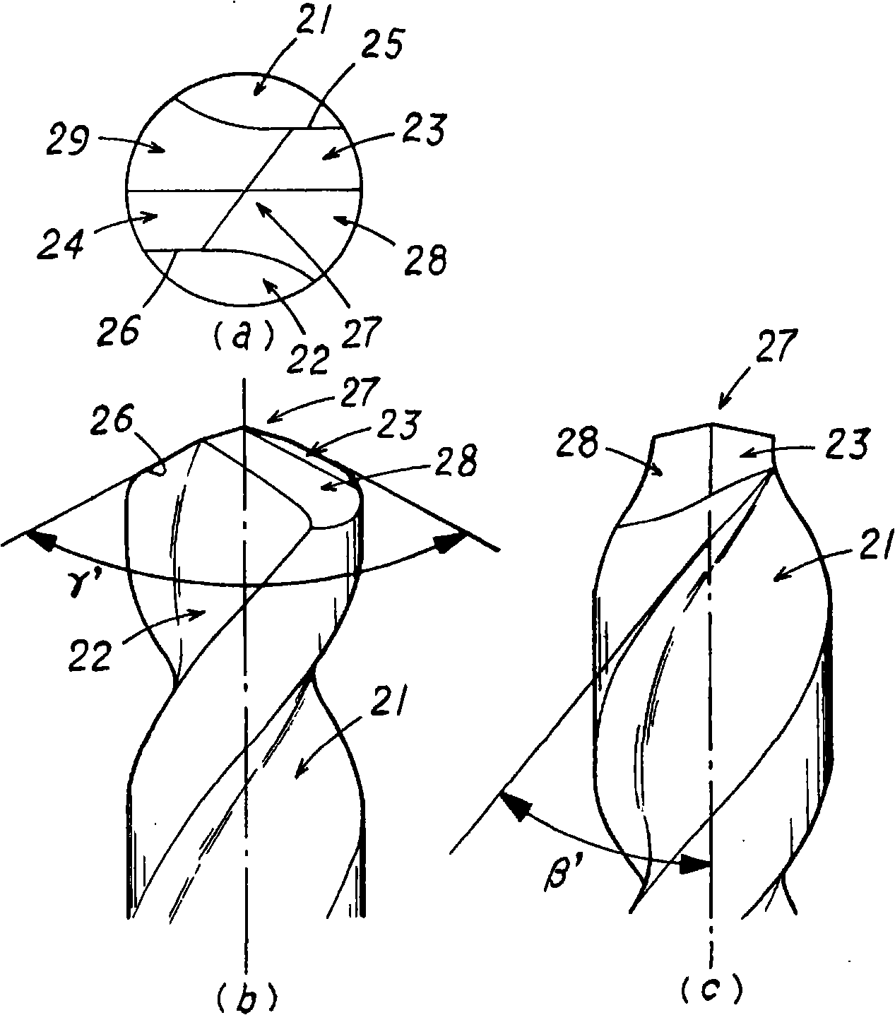
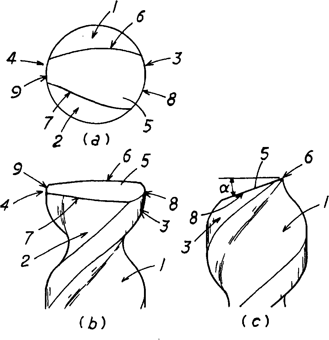
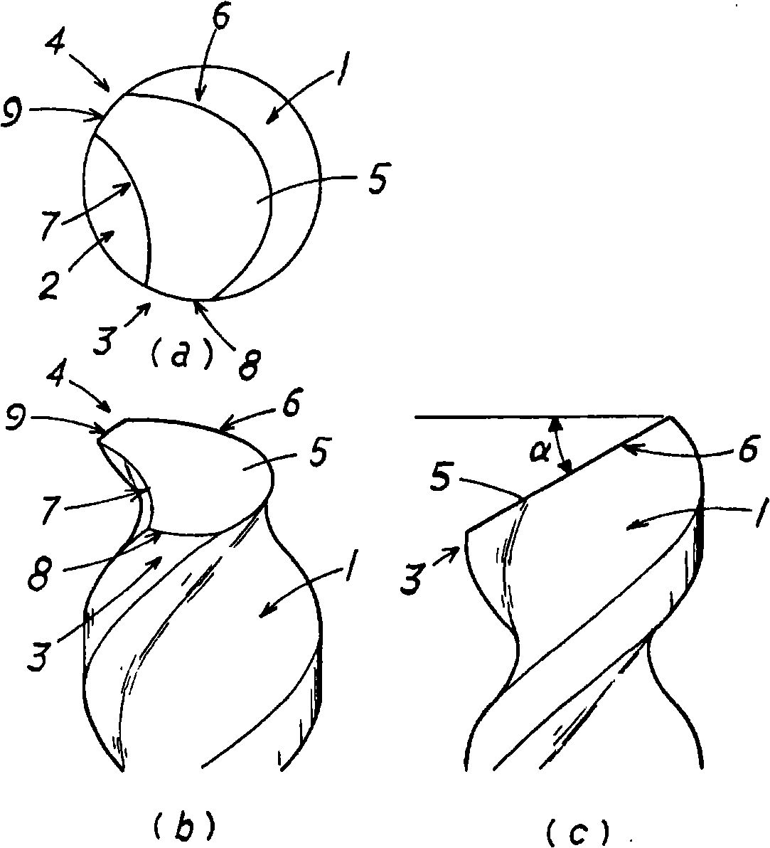
[0036] The drilling tool of the present invention is provided with a flat drill point surface 5 without ridges at the tool tip, and has a chisel edge near the center of the tool tip, for example, and is connected to the chisel edge to form a predetermined drill point angle. The cutting edge of the ordinary drill bit is different, and the thrust direction (the axial direction of the tool) is used to bear most of the cutting resistance during the hole machining process, so as to reduce the external force in the direction at right angles to the tool axis (the cutting force during the hole machining process). The bending stress generated by the resistance) is not easy to break.

[0037] Furthermore, cutting is gradually performed while the most protruding part of the drill point surface 5 (the crossing ridge with the land portion or...


PUM


Abstract

The invention provides an unprecedented drilling tool of strong usefulness. Despite a very small diameter, the drilling tool has no tendency to break, so frequent replacement is no use . Production and inspection can be readily managed due to a simple shape of the drilling tool which has one or plural spiral-shaped scrap exhaust grooves (1, 2). A flat drill point surface(5) not provided with a crest line placed crosswise to a tool central axis, is arranged on the top part of the drilling tool.

Description

technical field [0001] The invention relates to a drilling tool. Background technique [0002] Drilling bits for common printed wiring boards (PCB), such as figure 1 As shown, a pair of chip discharge flutes 21, 22 are provided at a predetermined helix angle (ねじれ angle) β, and the intersecting ridgeline portions 25, 26 of these chip discharge flutes 21, 22 and the first flank surfaces 23, 24 A cutting edge having a predetermined point angle γ' is formed. Numbers 28 and 29 are the second flank among the figures. [0003] therefore, figure 1 The tool has four point faces in total, and the chisel edge 27 is formed near the center of the point of the tool by making each point face (relief face) have a predetermined angle. in addition, figure 1 (a) is a top view, 1(b) is a front view, and 1(c) is a right side view. [0004] However, with the high integration and high density of electronic equipment in recent years, it is necessary to process holes with extremely small diame...

Claims


Application Information

Patent Timeline
Patent Type & Authority Applications(China)
IPC IPC(8): B23B51/00
CPCH05K3/0047B26F1/16B26F2210/08B23B2251/04B23B51/011
Inventor 大内清明风间悠作山贺拓真
Owner UNION TOOL
Why Eureka
Try Eureka