Powershift transmission clutch system with a predetermined running clearance

A technology for power shifting and running gaps, which is applied to fluid-driven clutches, non-mechanical driven clutches, clutches, etc., and can solve problems such as increased windage loss in running gaps, low efficiency of brake disc heat generation, and excessive running gaps.

Inactive Publication Date: 2008-12-03
DEERE & CO
View PDF0 Cites 8 Cited by
  • Summary
  • Abstract
  • Description
  • Claims
  • Application Information

AI Technical Summary

Problems solved by technology

The running clearance between some clutch plates during their disabled state requires the following to be minimized: 1) clutch plate friction, 2) brake disc wear, and 3) heat generation and inefficiency due to brake disc resistance
In addition, insufficient running clearance increases windage losses due to leakage of hydraulic fluid through the small gaps between the clutch plates
[0008] Additionally, excessive running slack is undesirable for the following reasons: 1) there is a delay due to hydraulic clutch piston movement to fully engage the clutch, thereby affecting transmission shift quality; 2) worst case scenarios (tolerance buildup) require more Multiple axial spaces to accommodate components; and 3) This extra distance requires more hydraulic fluid to move the hydraulic clutch piston

Method used


Image

  • Powershift transmission clutch system with a predetermined running clearance
  • Powershift transmission clutch system with a predetermined running clearance
  • Powershift transmission clutch system with a predetermined running clearance

Examples


Embodiment Construction

[0017] specific implementation plan

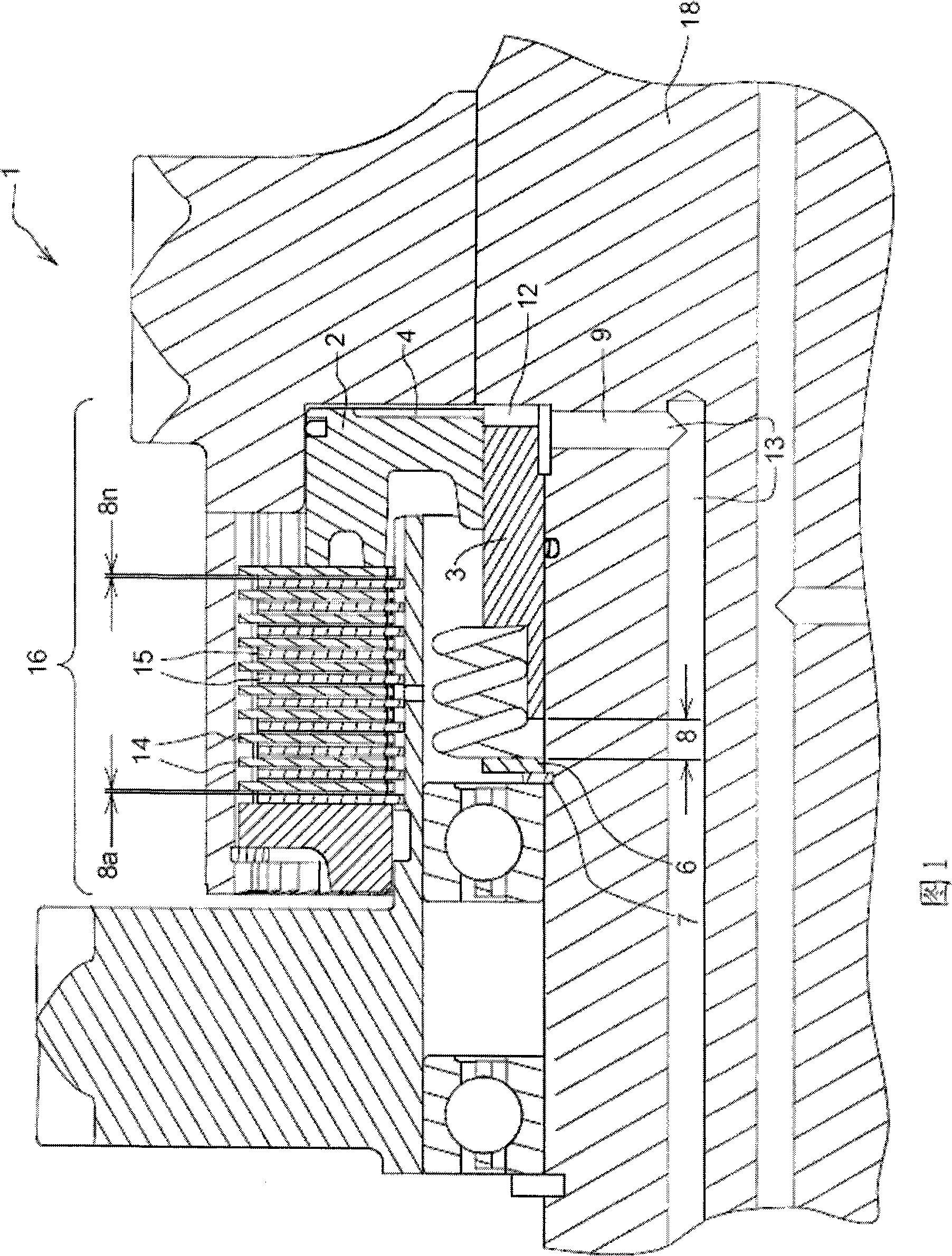
[0018] Referring to Figure 1, an embodiment of the invention is shown using a simple clutch piston puller system comprising a hydraulic clutch piston 2 and a sleeve 3 which is press fit over the hydraulic clutch piston 2 On the cylinder, the sleeve 3 is automatically adjusted and positioned to control the clutch running gap 8 to a predetermined amount, no matter how much wear the clutch separator 14 and friction plate 15 have accumulated.

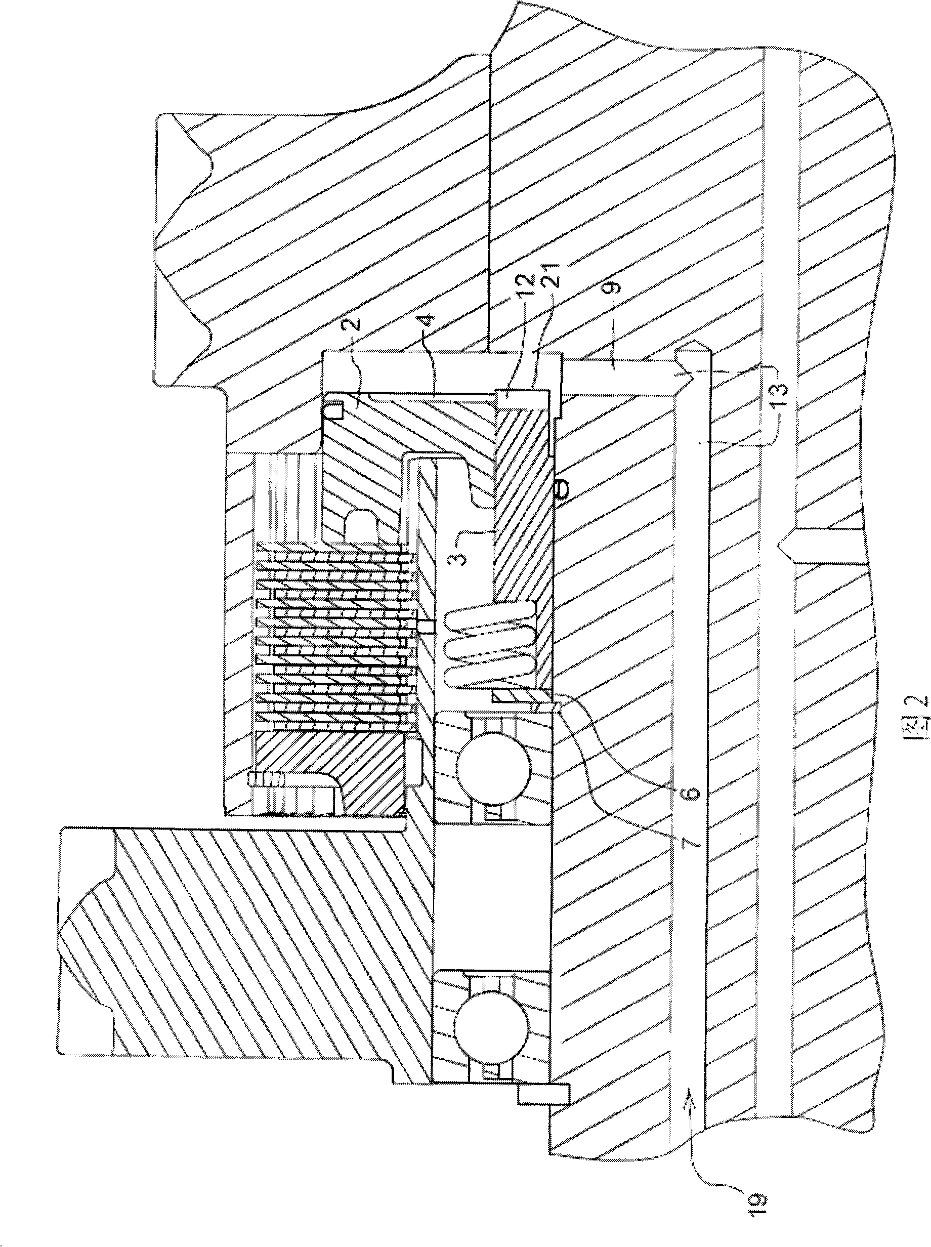
[0019] Inside the clutch housing 16 is a sleeve 3 that is press fit over the hydraulic clutch piston 2 cylinder and both are shaped to run together and slide relative to each other in normal operation for adjustment to maintain optimum overall running clearance 8. The total running gap 8 here is the sum of the individual running gaps between spacer disk 14 and friction lining 15 from 8a to 8n. When the clutch 1 is powered, as shown in Figure 2, the pressurized hydraulic fluid 13 or clutch lubricating ...


PUM


Abstract

The present invention relates to a powershift transmission clutch system with a predetermined running clearance. A simplified and improved clutch piston, retractor system is provided for controlling the running clearance of clutch plate(s) to minimize windage loss and to improve transmission shift quality. This improved shift quality helps improve operator's comfort reduce shock loads on power transmission components, and reduce the energy input to the clutches when changing gears during the acceleration and deceleration of the vehicle. The clutch piston retractor system is self adjusting to accommodate wear to the clutch disks and optimize the shift quality, while compensating for the additional travel distance. Thus, the need to periodically recalibrate the entire system is eliminated.

Description

technical field [0001] This invention relates generally to automotive transmission clutch systems, and more particularly to an apparatus for maintaining preferred clutch plate running clearances to minimize windage losses and improve transmission shift quality. Background technique [0002] Powershift (Powershift) gearbox clutches are generally used in various working vehicles. A powershift transmission clutch generally consists of: a clutch drum (driver or driven member) having an expandable piston-running fluid tank or piston chamber; a piston against which the piston-running piston chamber axially movably arranged; a clutch hub (driver) coaxially arranged in the clutch drum; and a clutch plate set, which is arranged between the clutch drum and the clutch hub, with one end pointing to the piston. The clutch plate pack includes alternately juxtaposed first and second sets of clutch plates. When pressurized working fluid is injected into the piston cavity, the piston is fo...

Claims


Application Information

Patent Timeline
Patent Type & Authority Applications(China)
IPC IPC(8): F16D25/08
CPCF16D25/0638F16D25/126
Inventor 托马斯·哈格·武克雷格·R·艾克乔·R·格雷
Owner DEERE & CO
Why Eureka
Try Eureka