Magnetic coupling resonance vibration type wireless energy transform device

A wireless energy transmission, resonant technology, applied in circuit devices, electromagnetic wave systems, electrical components, etc., can solve problems such as the transmission distance that cannot pass through intermediate obstacles

Inactive Publication Date: 2008-12-03
HARBIN INST OF TECH
View PDF0 Cites 55 Cited by
  • Summary
  • Abstract
  • Description
  • Claims
  • Application Information

AI Technical Summary

Problems solved by technology

[0006] The present invention is to solve the shortcomings of the existing wireless energy transmission technology that cannot pass through

Method used


Image

  • Magnetic coupling resonance vibration type wireless energy transform device
  • Magnetic coupling resonance vibration type wireless energy transform device
  • Magnetic coupling resonance vibration type wireless energy transform device

Examples


specific Embodiment approach 1

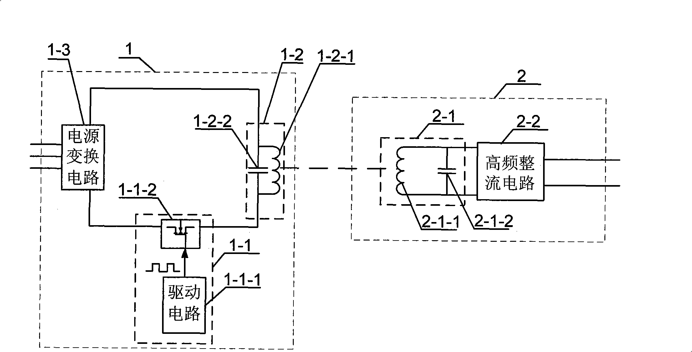
[0017] Specific implementation mode one: combine figure 1 Describe this embodiment, this embodiment is made up of energy transmitting source 1 and energy receiver 2;

[0018] The energy emission source 1 is composed of a magnetic field resonance excitation and drive circuit 1-1 and a resonance emission circuit 1-2;

[0019] The magnetic field resonance excitation and drive circuit 1-1 is composed of a drive circuit 1-1-1 and a drive switch tube 1-1-2, and the drive circuit 1-1-1 generates a signal that is the same as the set resonant emission frequency or is the resonant emission frequency 1 / n driving signal, drive switch tube 1-1-2 to receive the drive signal; the switching frequency of drive switch tube 1-1-2 is the same as the resonant transmission frequency or 1 / n of the resonant transmission frequency, which is used to convert the power supply Energy is supplemented to the resonant transmitting circuit 1-2, wherein n is a positive integer;

[0020] The resonant transmit...

specific Embodiment approach 2

[0024] Specific implementation mode two: combination figure 1 Describe this embodiment, the difference between this embodiment and the specific embodiment is that the energy emission source 1 adds a power conversion circuit 1-3, and the power conversion circuit 1-3 is used to convert alternating current into direct current and transmit it to magnetic resonance excitation and drive The circuit 1-1 and the resonant transmitting circuit 1-2; other composition and connection methods are the same as those in the first embodiment.

specific Embodiment approach 3

[0025] Specific implementation mode three: combination figure 1 Describe this embodiment, the difference between this embodiment and specific embodiment 1 is that the resonant transmitting coil 1-2-1 and the resonant transmitting capacitor 1-2-2 in the resonant transmitting circuit 1-2 are connected in series or in parallel; other components and The connection method is the same as that in the first embodiment.

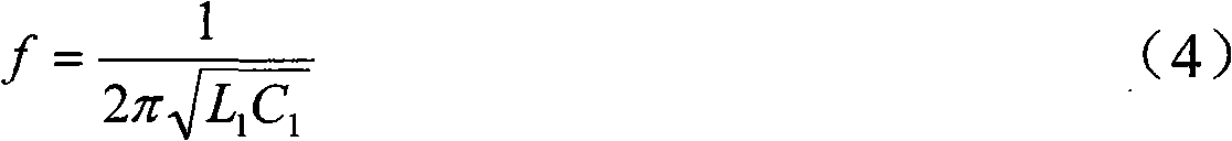
[0026] The resonant frequency of the resonant transmitting circuit 1-2 is determined by the following formula:

[0027] f = 1 2 π L 1 C 1 - - - ( 4 )

[0028] where C 1 It is the capacitance of the resonant emission capacitor 1-2-2. If there are multiple capacitors in th...


PUM

PropertyMeasurementUnit
Diameteraaaaaaaaaa
Diameteraaaaaaaaaa

Abstract

The invention provides a magnetic coupling resonance-typed wireless energy transmission device, relating to the field of wireless energy transmission and solving the shortage that the prior art can not carry out the transmission with the barrier or has short transmission distance. The magnetic coupling resonance-typed wireless energy transmission device consists of an energy emission source and an energy receiver; by virtue of the two electromagnetic systems with the same special resonance frequency, with a certain distance, the energy transmission is carried out as the resonance is generated owing to the identical vibration frequency. The energy emission source consists of a magnetic field resonance excitation and driving circuit and a resonance emission circuit; the resonance emission circuit consists of a resonance emission coil and a resonance emission capacitor; the energy receiver consists of a resonance receiving circuit and a high-frequency rectifier circuit; the resonance receiving circuit consists of a resonance receiving coil and a resonance receiving capacitor; the magnetic field is generated by the resonance emission coil; the resonance receiving coil and the magnetic field have the same oscillation frequency and generates the magnetic resonance; the energy in the resonance receiving coil is continuously collected and can be subsequently provided to the loads through the high-frequency rectifier circuit. The magnetic coupling resonance-typed wireless energy transmission device has the advantages of long transmission distance and no barriers.

Description

technical field [0001] The invention relates to the field of wireless energy transmission. Background technique [0002] At present, almost all electrical equipment must use tangible media (such as: using metal wires, wires and cables) as the main connection for power transmission or energy transmission, even for short-distance power transmission (such as computers, TVs, desk lamps, etc.) , It must also go through the cumbersome process of power line connection and laying or pulling wires, so that the placement of electronic and electrical equipment that needs to be powered by electricity is affected. If better wireless energy transmission technology and devices can be developed to achieve effective power transmission that is not affected by foreign objects or the surrounding environment, then the power transmission can be achieved through wireless transmission, then when using these electrical equipment, It must be more handy. In addition, it has very practical applicatio...

Claims


Application Information

Patent Timeline
IPC IPC(8): H02J17/00H02J50/12
Inventor 朱春波刘凯于春来逯仁贵任立涛赵小坤
Owner HARBIN INST OF TECH
Why Eureka
Try Eureka