Suction nozzle and surface mounting machine

A technology of adsorption surface and nozzle seat, applied in the direction of electrical components, electrical components, etc., to achieve the effect of easy cleaning operation, reduced operation frequency, and shortened cleaning time

Active Publication Date: 2008-12-03
YAMAHA MOTOR CO LTD
View PDF1 Cites 18 Cited by
  • Summary
  • Abstract
  • Description
  • Claims
  • Application Information

AI Technical Summary

Problems solved by technology

However, since the above-mentioned pins are attached to the nozzle holder by screws, tools such as a screw

Method used


Image

  • Suction nozzle and surface mounting machine
  • Suction nozzle and surface mounting machine
  • Suction nozzle and surface mounting machine

Examples


no. 1 Embodiment approach

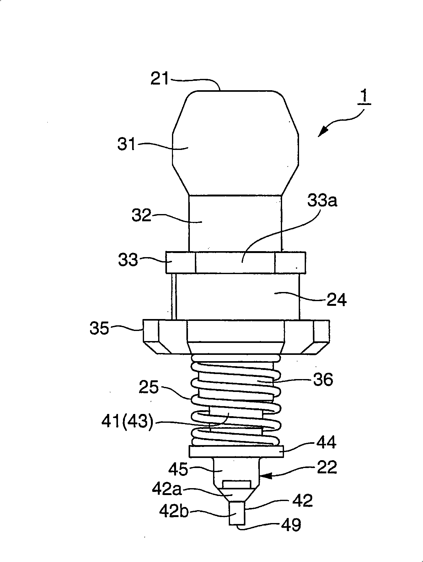
[0038] Below, combine Figure 1 to Figure 14 , and an embodiment of the suction nozzle according to the present invention will be described in detail.

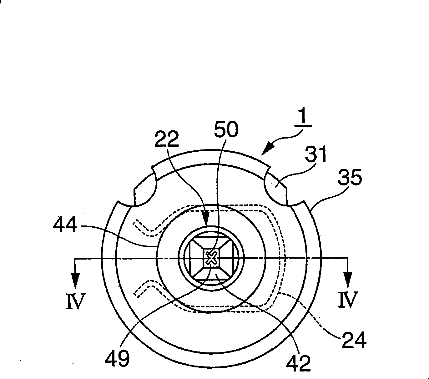
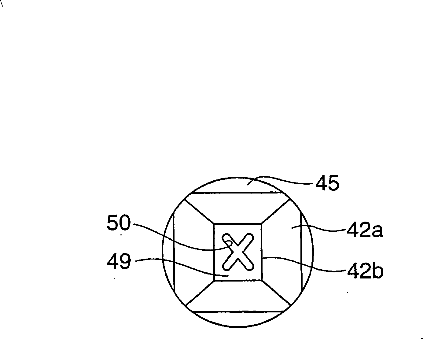
[0039] figure 1 is a side view of the suction nozzle related to the present invention, figure 2 is the bottom view of the nozzle, image 3 is an enlarged view of the component adsorption surface, Figure 4 is a longitudinal sectional view of a suction nozzle related to the present invention, and is figure 2 Sectional view of line IV-IV.

[0040] Figure 5 is a schematic diagram of the clamping part, where (a) is a top view, and (b) is a side view. Image 6 (a) is a side view, (b) is a bottom view, (c) is a C-C line sectional view of (b), and (d) is a D-D line sectional view of (a). Figure 7 It is a schematic diagram of a suction nozzle main body, (a) of this figure is a side view, (b) is a B-B line cross-sectional view of (a).

[0041] Figure 8 It is a perspective view of a suction nozzle related to the present in...

no. 2 Embodiment approach

[0100] Suction nozzles can also be formed as Figure 15 Nozzle shown.

[0101] Figure 15 It is a cross-sectional view showing another embodiment of the suction nozzle. exist Figure 15 ,and Figure 1 to Figure 14The same or equivalent components as those described in the illustrated embodiments are denoted by the same reference numerals, and detailed description thereof will be appropriately omitted.

[0102] Figure 15 In the shown nozzle 1 , the elongated hole 51 serves as an engaging portion of the nozzle body side 22 engaged with the pin 23 . That is, on the shaft member 41 of the nozzle main body 22 of this embodiment, at the position corresponding to the pin hole 37 of the nozzle holder 21, a long shaft is formed that is long in the vertical direction (the axial direction of the nozzle holder 21). Hole 51.

[0103] The elongated hole 51 is passed through the fitting cylinder 43 of the nozzle body 22 in a state of penetrating the fitting cylinder 43 in a direction...


PUM


Abstract

The invention provides a suction nozzle and a surface assembling machine. The suction nozzle comprises: a suction nozzle body (22) with an element absorption plane (49) and an air passage, an embedded hole (26) embedded in the suction nozzle body (22), a suction nozzle seat (21) arranged on the absorption head (3), a pin (23) blocked with the block groove (48) of the suction nozzle body (22) and limiting the suction nozzle body (22) only to move in a prescribed movement amount, and a compression spring (25) acting on the suction nozzle body (22). The compression spring (25) at the outside of the suction nozzle body (22) is elastically arranged between the suction nozzle body (22) and the suction nozzle seat (21). The block groove (48) is formed at the outside of the air passage (47) on the suction nozzle body (22). The pin (23) is supported on the suction nozzle seat (21) in a state of blocking with the block groove (48) and passing across the embedded part of the suction nozzle seat (21) and the suction nozzle body (22). After the suction nozzle of the invention is used, the foreign matter is difficult to attach to the interior, thereby reducing the operation frequency of cleaning.

Description

technical field [0001] The present invention relates to a suction nozzle capable of alleviating the impact when picking up an electronic component or alleviating the impact when mounting the electronic component on a printed wiring board, and a surface mounter including the same. Background technique [0002] Conventional suction nozzles of this type are those disclosed in Patent Document 1 (Japanese Patent Laid-Open Publication No. 2006-093248). The suction nozzle disclosed in Patent Document 1 includes: a suction nozzle main body for absorbing electronic components; a suction nozzle holder mounted on the suction head of a surface mounter while maintaining the suction nozzle main body; Mouth body so that it tends to compress the coil spring underneath. [0003] The nozzle main body is composed of a cylindrical body with a component suction surface formed at one end (lower end) and an air passage formed inside, and is movably fitted in a hole formed in the nozzle holder. O...

Claims


Application Information

Patent Timeline
IPC IPC(8): H05K13/04
Inventor 秋吉洋
Owner YAMAHA MOTOR CO LTD
Why Eureka
Try Eureka