Power assembly of hybrid power automobile

A technology of hybrid electric vehicles and powertrains, which is applied in the field of powertrains of automobiles and can solve problems such as waste

Active Publication Date: 2008-12-10
CHERY AUTOMOBILE CO LTD
View PDF0 Cites 24 Cited by
  • Summary
  • Abstract
  • Description
  • Claims
  • Application Information

AI Technical Summary

Problems solved by technology

[0003] The technical problem to be solved by the present invention is to design a powertrain of a hybrid electric vehicle. When the motor alone dri

Method used


Image

  • Power assembly of hybrid power automobile
  • Power assembly of hybrid power automobile
  • Power assembly of hybrid power automobile

Examples


Embodiment Construction

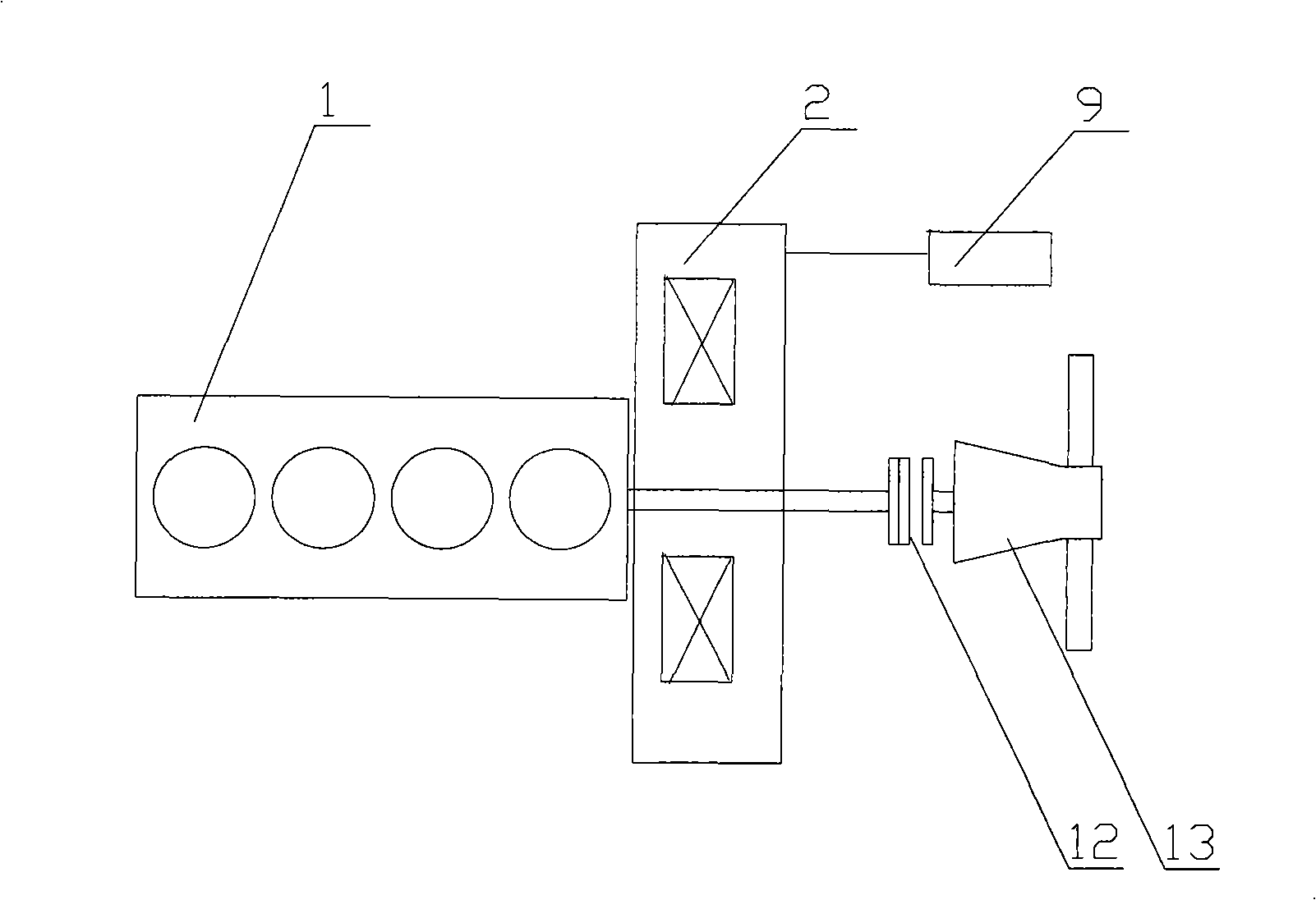
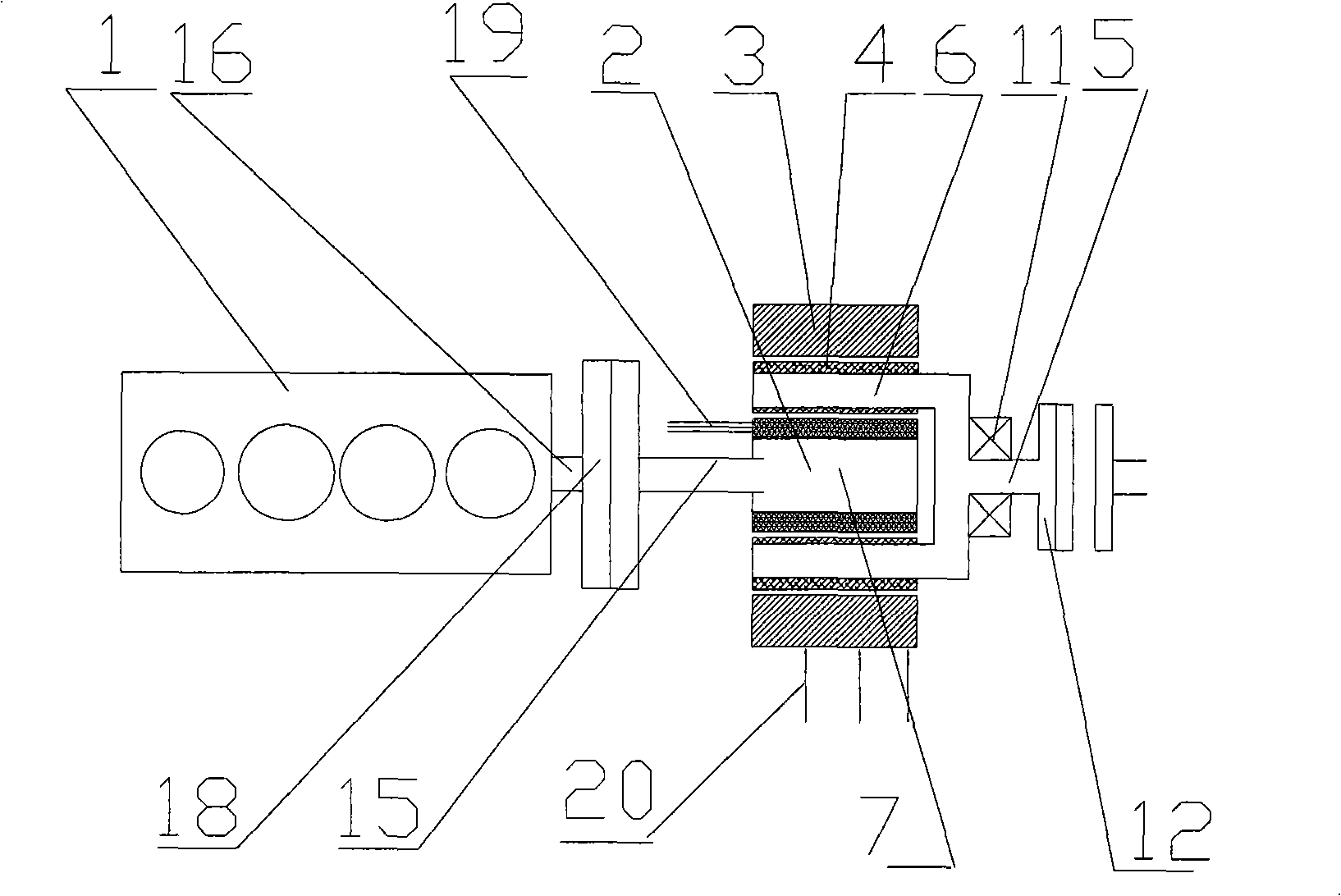
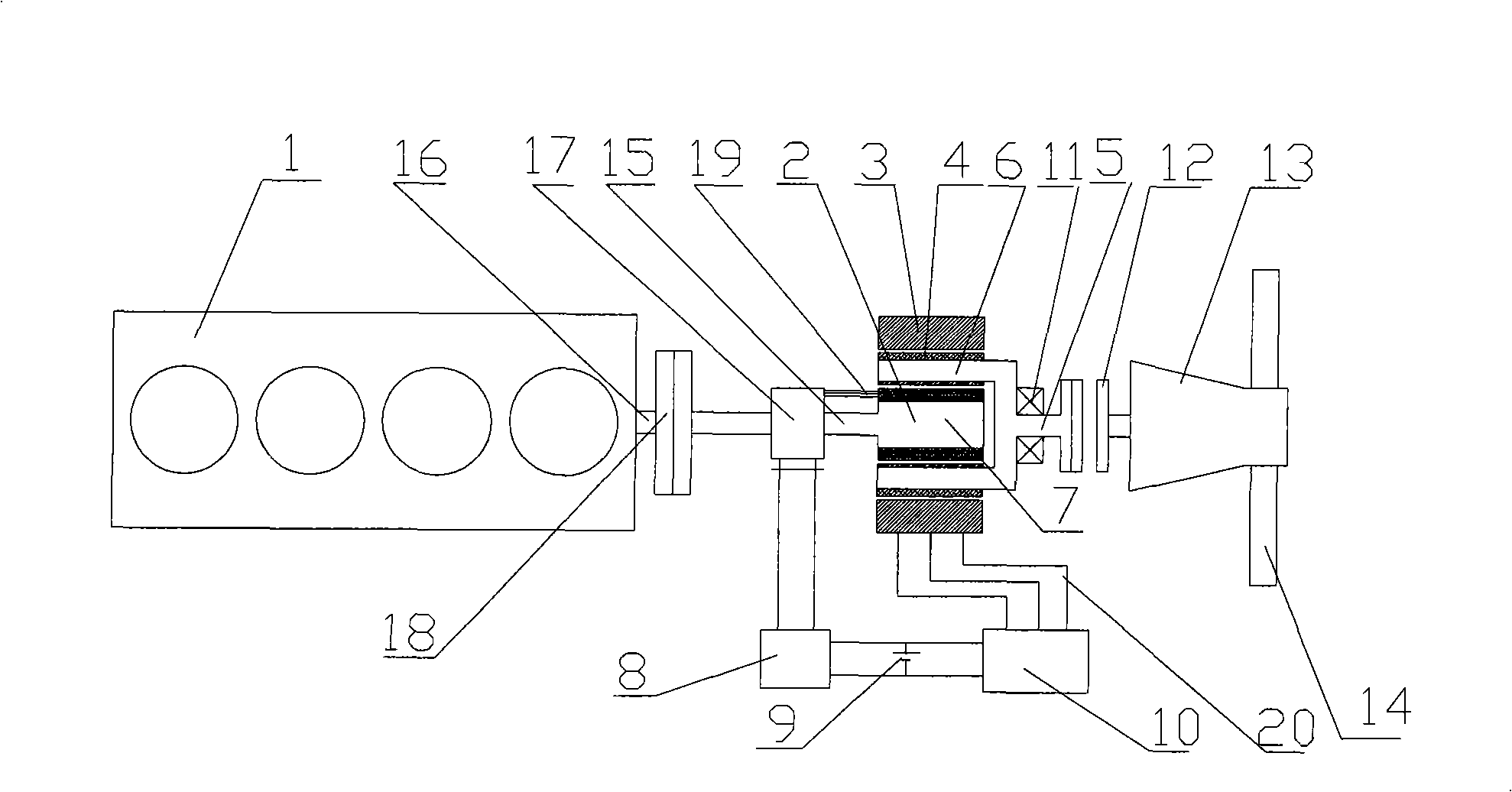
[0012] like figure 2 As shown, it is a connection diagram of a power assembly and an external power supply system of a hybrid electric vehicle, including an engine 1, a motor 2, and the motor 2 is a dual-rotor motor, including a casing, a stator 3, an outer rotor 6, and an inner rotor 7 , the stator (3) is a wound stator with a terminal 20 for external power supply of the stator, the outer rotor 6 is a permanent magnet rotor, and its inner and outer surfaces are inlaid with magnetic steel 4, and the inner rotor 7 is a wound rotor with an outer connection of the inner rotor The terminal 19 of the power supply is in the casing, the outer rotor 6 is installed in the stator 3, the inner rotor 7 is installed in the outer rotor 6, the output shaft 5 of the inner rotor 7, the outer rotor 6 and the output shaft 16 of the engine 1 are coaxial, and the outer rotor 7 is installed in the outer rotor 6. The output shaft 5 of the rotor 6 is connected with the driving end of the clutch 12 o...


PUM


Abstract

The invention discloses a power assembly of a hybrid electric vehicle which includes an engine, a double-rotor motor, a battery, etc. The power assembly of a hybrid electric vehicle is characterized in that the double-rotor motor includes a stator and a loop, an outer rotor, an inner rotor and a loop; a stator loop is twisted on the stator and surrounds the periphery of the outer rotor; the innersurface and the outer surface of the outer rotor are embedded with alnico; the loop of the inner rotor is twisted on the inner rotor; the inner rotor of an output shaft, the outer rotor and the stator are coaxial with the output shaft of the engine. The output shaft of the outer rotor is supported on a shell by a bearing and is connected with the drive end of a clutch; the inner rotor is fixed with the output shaft of the engine from the other end; the battery is respectively and electrically connected with the stator loop and the loop of the inner rotor. The power assembly of a hybrid electric vehicle can be utilized not to drive the engine to rotate idly when the vehicle is driven singly by the motor or by the power generated from regenerative braking.

Description

technical field [0001] The invention relates to a power system of an automobile, in particular to a power assembly of a hybrid electric automobile driven jointly by an internal combustion engine and an electric motor. Background technique [0002] At present, hybrid vehicles with pure electric drive mode often use two motors and have complex power coupling mechanisms to realize many functions such as power generation, driving, and starting the engine, which increases the cost and causes the system to be complicated. much space. Therefore people design the electric motor to be integrated between the engine and the gearbox, set the drive, generate electricity and start the engine function in one, and coaxial with the output shaft and the hybrid vehicle of the gearbox input shaft, "Automotive Engine" magazine 2007 2 A series of articles titled "Design of Single-shaft Parallel Hybrid Powertrain" was published in the first issue published in May, which announced a parallel hybri...

Claims


Application Information

Patent Timeline
IPC IPC(8): B60K6/26H02K7/14H02K7/18H02K16/02
Inventor 李明军
Owner CHERY AUTOMOBILE CO LTD
Why Eureka
Try Eureka