
Plasma chemical vapor deposition vacuum apparatus for photovoltaic assembly scale manufacture

A chemical vapor deposition, plasma technology, applied in gaseous chemical plating, metal material coating process, coating and other directions, can solve the problem of low pass rate, increase the production line process, unstable electrode radio frequency glow, etc. To achieve the effect of reducing manufacturing costs, reducing the number of equipment, and reducing construction costs

Inactive Publication Date: 2008-12-10
SUZHOU SPRUCE PHOTOVALAIC ENERGY TECHSE INC
View PDF0 Cites 1 Cited by
  • Summary
  • Abstract
  • Description
  • Claims
  • Application Information

AI Technical Summary

Problems solved by technology

[0003] The disadvantage of the prior art is that each time before deposition, the electrode box containing the glass to be deposited needs to be preheated by other devices, then pushed into the deposition chamber, and then the electrodes of the electrode box are installed; , and it is necessary to remove the electrodes of the electrode box of the deposited amorphous silicon thin film solar cell, pull the electrode box out of the vacuum chamber, and cool it in other auxiliary devices
Such frequent loading and unloading of the electrode joints will have a bad influence on the contact of the electrodes. Poor contact of the electrodes will lead to the instability of the radio frequency glow, resulting in a low pass rate in the production process.
At the same time, the existing system also adds additional preheating devices and cooling devices, which increases the process of the assembly line in the production line.

Method used


Image

  • Plasma chemical vapor deposition vacuum apparatus for photovoltaic assembly scale manufacture
  • Plasma chemical vapor deposition vacuum apparatus for photovoltaic assembly scale manufacture
  • Plasma chemical vapor deposition vacuum apparatus for photovoltaic assembly scale manufacture

Examples


Embodiment

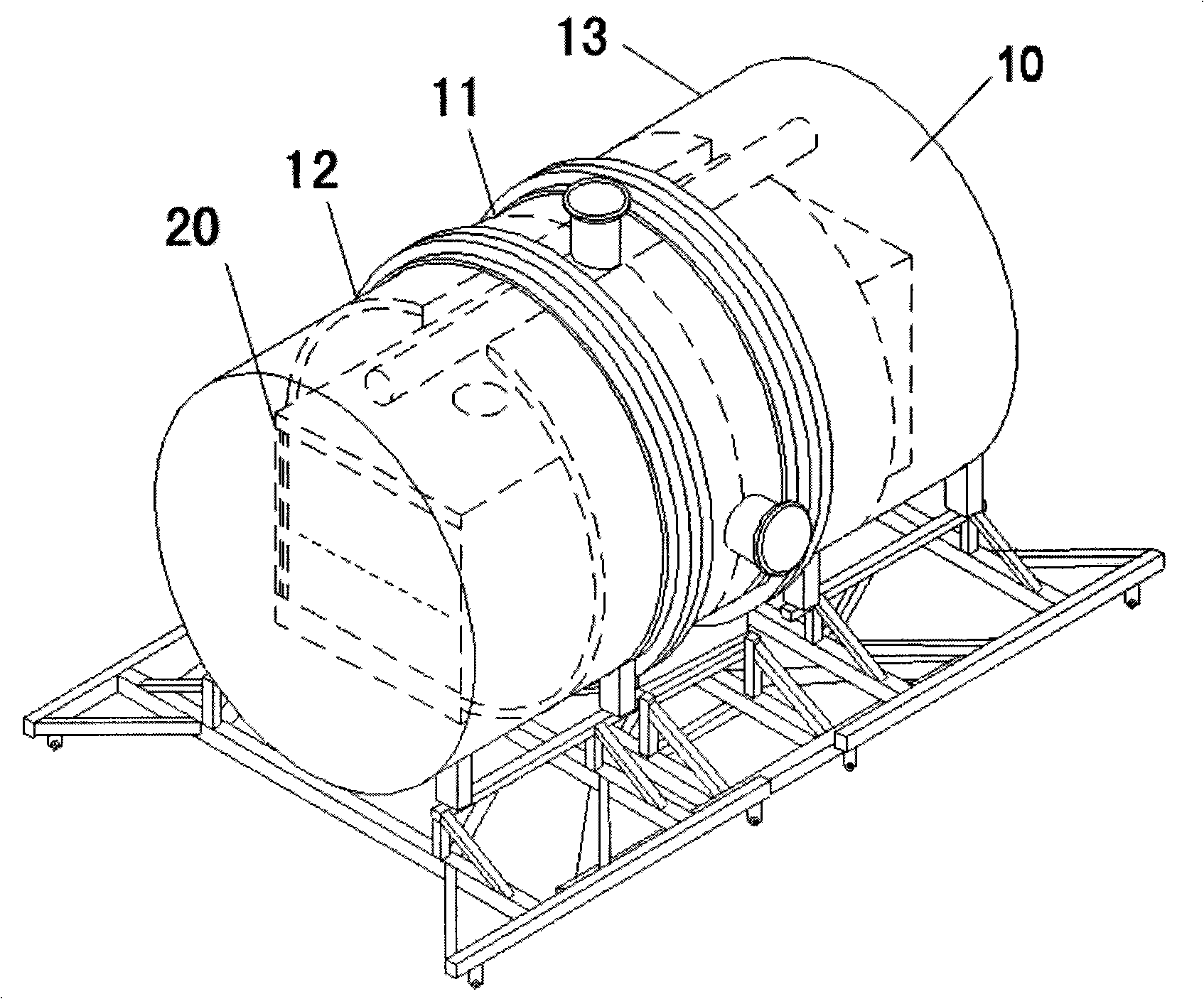
[0022] Such as figure 1 , figure 2 As shown, a plasma chemical vapor deposition vacuum equipment for large-scale manufacturing of photovoltaic modules includes a vacuum chamber 10 and an electrode box 20 .

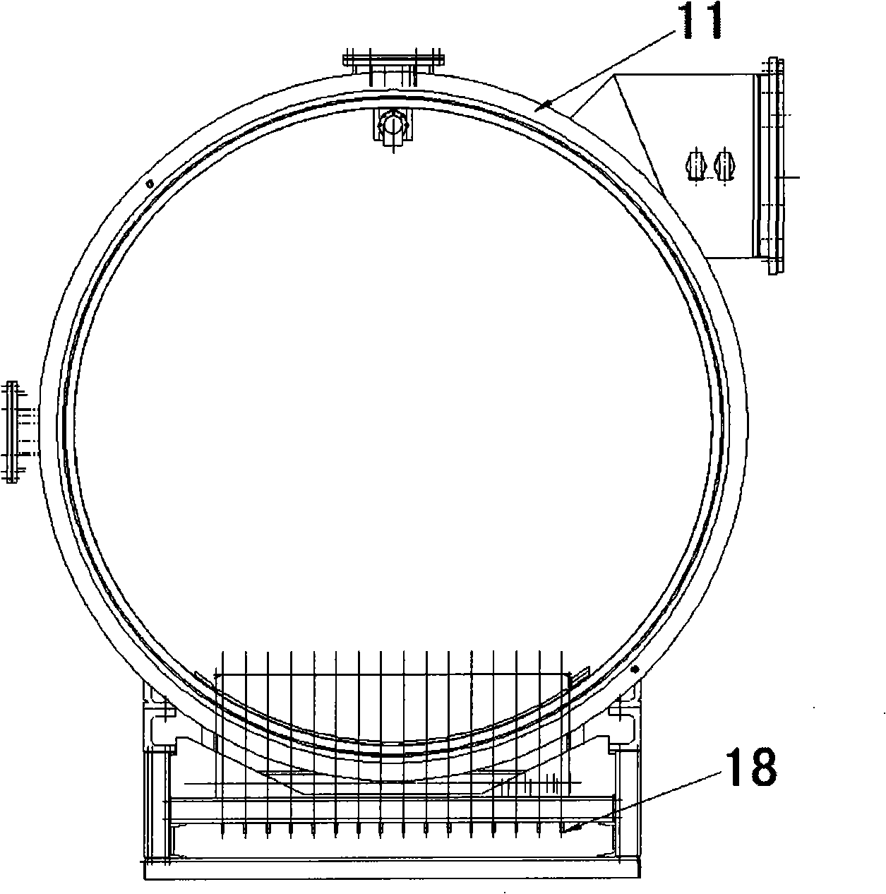
[0023] refer to figure 2 , The vacuum chamber 10 is a detachable vacuum chamber, which includes a relatively fixed main body portion 11 located in the middle section and detachable portions 12, 13 respectively located at both ends. The main body 11 and the detachable parts 12 and 13 at both ends can be sealed to form a vacuum chamber when required for work, and can also be separated when loading and unloading deposited products.

[0024] refer to figure 1 , figure 2 , the electrode box 20 is installed in the vacuum chamber 10 , and remains relatively stationary with the main body 11 of the vacuum chamber 10 before, during and after deposition.

[0025] Such as image 3 As shown, the main body 11 of the vacuum cavity 10 is provided with a radio frequency introducti...


PUM


Abstract

The invention discloses a plasma chemical vapor deposition vacuum apparatus for the scale manufacture of photovoltaic modules, comprising a vacuum cavity body (10) and an electrode box (20). The vacuum cavity body (10) is a separable vacuum cavity body which comprises a main part (11) positioned in the middle section of the vacuum cavity body and separable parts (12 and 13) respectively positioned at two ends of the vacuum cavity body. The main part (11) and the separable parts (12, 13) at two ends of the vacuum cavity body can encloses an airtight vacuum cavity body and can be separated from each other for loading and unloading the deposition products, the electrode box (20) is arranged inside the main part (11) of the vacuum cavity body and keeps relative static to the main part (11) of the vacuum cavity body. By moving a part of the vacuum cavity body, the invention is free from the motion of the electrode box, thereby avoiding severe damages caused by frequent contact in loading and unloading of the electrode, and the reduction in the qualification rate of product caused by the unstable radio frequency glow due to the damage of the electrode. Besides, the vacuum apparatus has simple structure and lowers the manufacture cost.

Description

technical field [0001] The invention relates to the field of photovoltaic module manufacturing, in particular to a plasma chemical vapor deposition vacuum equipment for large-scale manufacturing of photovoltaic modules. Background technique [0002] In the prior art, plasma chemical vapor deposition vacuum equipment used for large-scale manufacturing of photovoltaic modules includes main components such as vacuum deposition chambers and electrode boxes. A deposition electrode box contains multiple radio frequency electrodes, and each electrode can deposit 4 solar cells. Put the preheated electrode box into a vacuum deposition chamber, and complete the deposition of amorphous silicon thin film solar cells in the vacuum chamber. After the deposition is complete, the electrode box is taken out for cooling. [0003] The disadvantage of the prior art is that each time before deposition, the electrode box containing the glass to be deposited needs to be preheated by other devices...

Claims


Application Information

Patent Timeline
IPC IPC(8): C23C16/44
Inventor 奚建平周子彬
Owner SUZHOU SPRUCE PHOTOVALAIC ENERGY TECHSE INC
Learn More