Press forming and processing method for saving motor stator and rotor material as well as device

A motor stator and stamping processing technology, which is applied in the field of mechanical processing, can solve problems such as waste, and achieve the effects of reducing waste, improving material utilization, and high-speed continuous production

Active Publication Date: 2008-12-17
宁波康迪普瑞模具技术有限公司
View PDF0 Cites 13 Cited by
  • Summary
  • Abstract
  • Description
  • Claims
  • Application Information

AI Technical Summary

Problems solved by technology

[0002] When the existing stamping technology stamps large quantities of circular products such as stators and rotors with molds, the products are usually arranged side by side on the stamped strips in design. When leaving the factory, it is a large coil of about 1200-1250MM. When the motor stator and rotor stamping factory stamps products, due to the limitation of the tonnage of the mold and punc

Method used


Image

  • Press forming and processing method for saving motor stator and rotor material as well as device
  • Press forming and processing method for saving motor stator and rotor material as well as device
  • Press forming and processing method for saving motor stator and rotor material as well as device

Examples


Embodiment 1

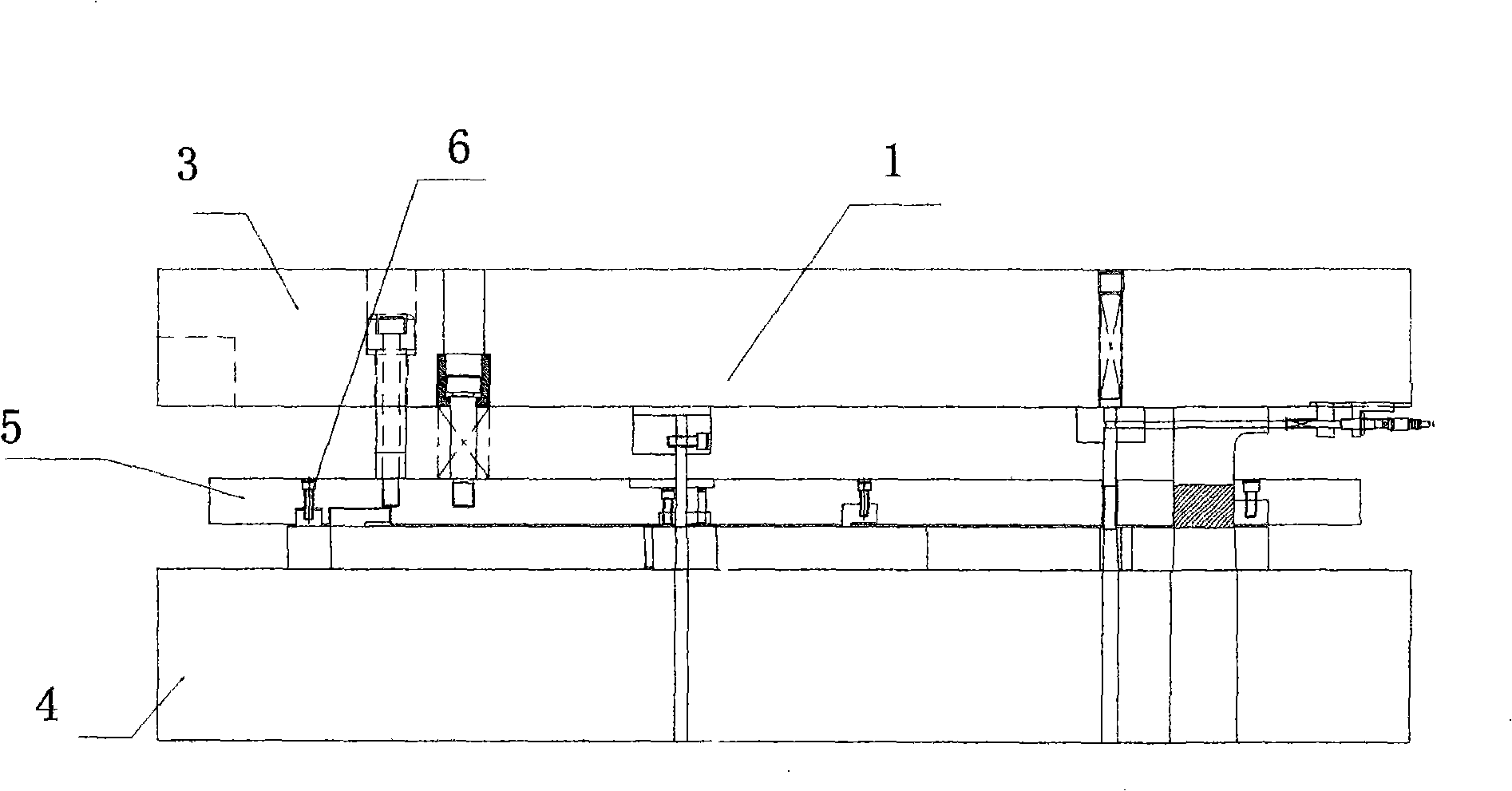
[0025] Embodiment 1: as figure 1 Shown, mold comprises upper mold base 3, lower mold base 4, guide plate 5, screw 6, and guide plate 5 is installed between upper mold base 3 and lower mold base 4, is fixed on the lower mold base 4 by screw 6.

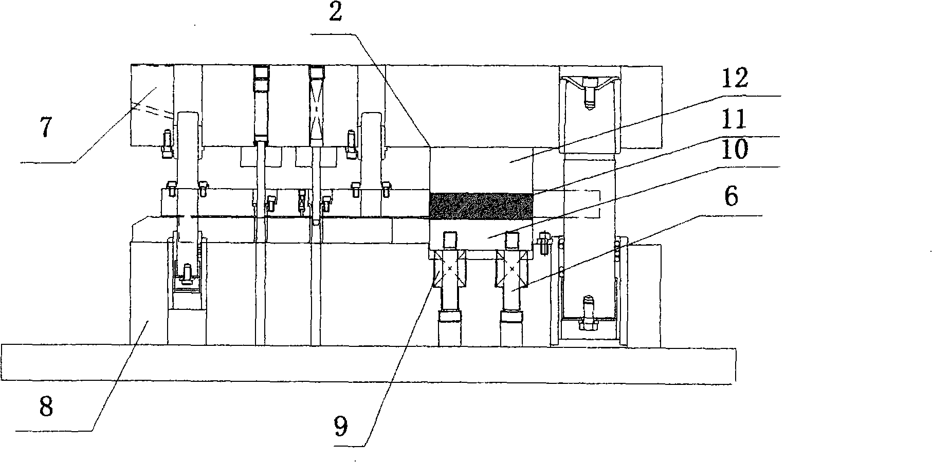
[0026] like figure 2 As shown, the mold includes an upper mold holder 7, a lower mold holder 8, an elastic body 9, a supporting plate 10, a punch 11, a pad 12, and a screw 6, and the lower mold fixing base 8 is equipped with a supporting plate 10, and the supporting plate 10 Elastomer 9 is housed between lower mold holder 8, fixed by screw 6, punch 11 is housed on the supporting plate 10, pad 12 is housed on the punch 11.

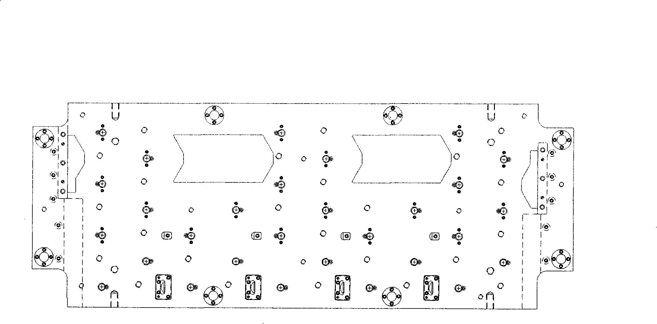
[0027] like image 3 As shown, the mold has stamping wavy edges and punching and cutting punches and dies for each column.

Embodiment 2

[0028] Embodiment 2: A stamping process method for motor stator and rotor materials, comprising the following steps:

[0029] Step 1: Stator and rotor stamping dies are generally single-row or double-row, and the number of stamping rows for wave-shaped materials (based on 1200-1250MM large coil materials) is determined according to single-row or double-row;

[0030] Figure 8 and Figure 9 It is a schematic diagram and comparison between the layout of the stamped workpiece in the present invention and the traditional layout.

[0031] like Figure 8 The determined number of columns is 2, and the edge is 1.5MM, and the positions of the workpieces to be stamped are arranged in a cross, such as Figure 8 As shown, according to the 1210MM wide material design, the raw materials can be fully utilized.

[0032] Figure 8 Take the strip width of 1210mm as an example: in the case of the same strip width, Figure 8 The method of punching flower material can punch out 5 flower mate...


PUM


Abstract

The invention relates to a stamping processing method and a device thereof, which can save the materials of a motor stator and a motor rotor. A high speed stamping method is used for solving the problem for cutting grail coil stocks and leading the edge waste material and the material between line and line of the traditional material cutting method to be fully utilized, thus achieving the goal of greatly improving the operating factor of the material and reducing the cost waste. The quantities of lines are confirmed according to the specifications of the products needing to be stamped; the position of a punch is fixed; the materials are automatically transmitted; the grail coil stocks purchased by a steel factory are fed into a die; a meniscate hole is firstly stamped at the set position surrounding the stamped products so as to release the stress; the structures of a convex die and a concave die which are combined with 'stamping' and 'cutting' are adopted; a material splint is arranged on the fixing seat of a lower die; an elastomer is arranged between the splint and the fixing seat of the lower die to realize continuous high speed production.

Description

technical field [0001] The invention relates to a stamping process method and structure of a high-speed progressive stamping die, in particular to a stamping process method and device for saving motor stator and rotor materials, and belongs to the field of mechanical processing. Background technique [0002] When the existing stamping technology stamps large quantities of circular products such as stators and rotors with molds, the products are usually arranged side by side on the stamped strips in design. When leaving the factory, it is a large coil of about 1200-1250MM. When the motor stator and rotor stamping factory stamps products, due to the limitation of the tonnage of the mold and punching machine, before production, according to the single-row or double-row production of the motor stator and rotor, plus 1.5-2MM The edge of the material is pre-cut into a straight material with a required width on the cutting machine with a roller knife (cutting process), so the edge ...

Claims


Application Information

Patent Timeline
IPC IPC(8): B21D22/02B21D37/10H02K15/02
Inventor 吴桂琴郝洁裴娟史众
Owner 宁波康迪普瑞模具技术有限公司
Why Eureka
Try Eureka