Flow guide and ultraviolet disinfecting reactor

A technology of ultraviolet disinfection and deflector, applied in the direction of light water/sewage treatment, etc., can solve the problem that the sterilization efficiency needs to be further improved, and achieve the effect of being easy to implement and popularize, easy to process and manufacture, and to increase the number of kills.

Inactive Publication Date: 2008-12-17
SICHUAN UNIV
View PDF0 Cites 2 Cited by
  • Summary
  • Abstract
  • Description
  • Claims
  • Application Information

AI Technical Summary

Problems solved by technology

Although this kind of reactor has a simple structure, its bactericidal efficiency needs to be further improved.

Method used


Image

  • Flow guide and ultraviolet disinfecting reactor
  • Flow guide and ultraviolet disinfecting reactor
  • Flow guide and ultraviolet disinfecting reactor

Examples


Embodiment 1

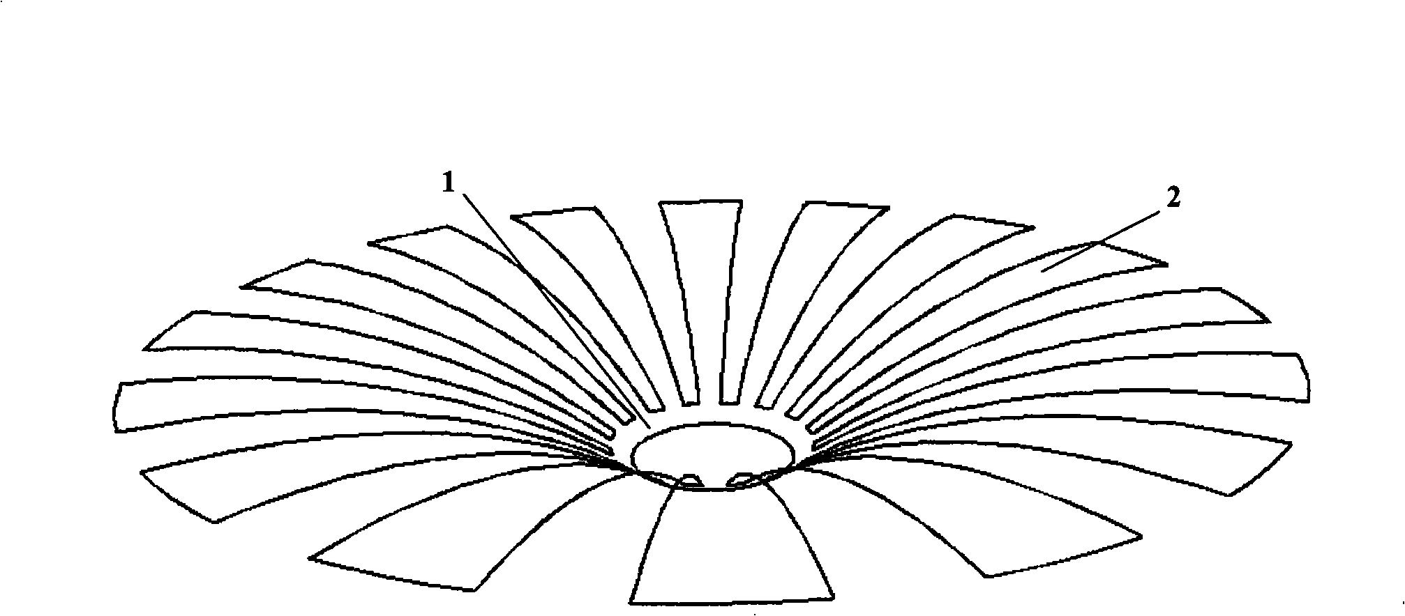
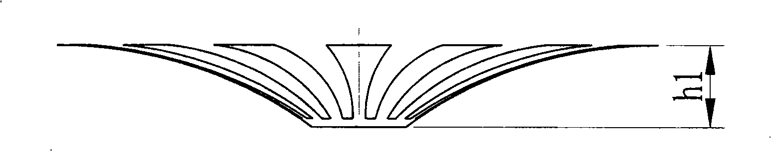
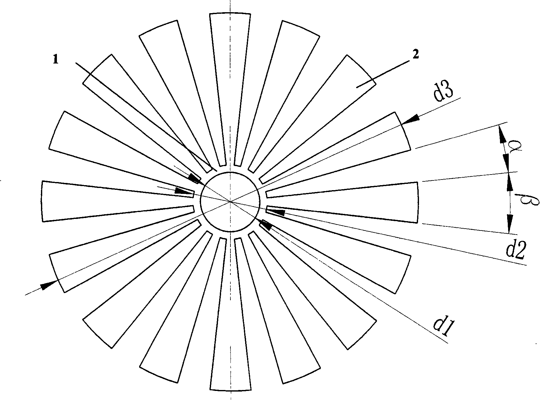
[0023] In this embodiment, the deflector is stamped and formed with stainless steel sheet, and its shape and structure are as follows figure 1 , figure 2 , image 3 As shown, it is composed of an upwardly curved arc ring 1 and sixteen arc-shaped pieces 2 with the same axial bending radius as the arc-shaped ring. The axial bending radius R of the arc-shaped ring 1 and the arc-shaped piece 2 is 36.0mm, The height h1 of the deflector 8 is 7.0 mm. The horizontal projection of each arc-shaped piece 2 is a partial ring, and its central angle β is 12.5°, and the central angle α of each arc-shaped piece 2 is evenly distributed along the periphery of the arc ring 1 and is an integrated structure with the arc ring. α is 10°. In the deflector, the inner diameter d1 of the circular arc ring 1 is 8.0 mm, the outer diameter d2 of the horizontal projection of the circular arc ring is 10.0 mm, and the diameter d3 of the horizontal projection of the arc-shaped piece is 50.8 mm.

Embodiment 2

[0025] In this embodiment, the structure of the ultraviolet disinfection reactor is as Figure 4 As shown, the shell 3, the shell cover 4 installed on the upper end of the shell, the ultraviolet lamp tube 9 installed on the shell cover and located in the shell, the lamp limiting spring 6 fixed on the inner wall of the shell and the shell cover 3 consists of a deflector 8 inside. The inner diameter of the housing 3 is D88.9mm and the height is 227mm. The water inlet at the bottom of the housing 3 is connected to the water inlet pipe 7, and the water outlet on the side wall of the housing 3 is connected to the water outlet pipe 5. The inner diameter d0 of the water inlet pipe 7 is 21.4mm, the inner diameter of the outlet pipe 5 is 22.0mm; the distance H between the lower end of the ultraviolet lamp tube 4 and the bottom of the housing 3 is 17mm; the deflector 8 has the shape, structure and size described in Example 1, and is installed in the ultraviolet lamp Below the tube 9 and abo...


PUM


Abstract

A fluid director comprises an upward-bended arc-ring and at least eight arc discs provided with the radius which is the identical to the axial-bended radius of the arc-ring, and a horizontal projection of each arc disc is a part of the ring, and the central angle is Beta, and the arc discs are equally distributed along the edge of the arc-ring at an interval of the central angle Alpha and are integrated with the arc-ring, wherein, Alpha is less than Beta. An ultraviolet disinfection reactor of the invention comprises a casing, a cover, an ultraviolet light tube, a light tube limiting spring and the fluid director with the above form. A water inlet is cut at the bottom of the casing, and a water outlet is cut on the side wall of the casing; the fluid director is arranged on the lower part of the ultraviolet light tube and on the upper part of the water inlet cut at the bottom of the casing. As the fluid director can change the flowing state of fluid and can increase the flowing time of fluid through a certain of path, then the fluid director is arranged in the ultraviolet disinfection reactor to prolong the retaining time of germ in a disinfection cavity so as to enhance the killing rate of germ or to enhance the water quantity to be disinfected with the same germ killing rate.

Description

Technical field [0001] The invention relates to a diversion device and an ultraviolet radiation disinfection device for changing the flow state of a water stream, in particular to an ultraviolet disinfection reactor and a diversion device which can enhance the germ killing efficiency when used in conjunction with it. Background technique [0002] Ultraviolet disinfection is a method of disinfection of drinking water. When germs in drinking water are irradiated by ultraviolet rays, the energy of the ultraviolet spectrum is absorbed by the DNA of the germs. When the radiation reaches a certain amount, the DNA structure of the germs is destroyed. To achieve the purpose of killing germs. [0003] It is understood that the existing ultraviolet disinfection reactor for drinking water disinfection includes a shell, a shell cover installed on the upper end of the shell, an ultraviolet lamp tube installed on the shell cover and located in the shell, and a lamp tube fixed on the inner wall...

Claims


Application Information

Patent Timeline
Patent Type & Authority Applications(China)
IPC IPC(8): C02F1/32
Inventor 周晓泉刘琳莉
Owner SICHUAN UNIV
Why Eureka
Try Eureka