Hydraulic expanding type movable joint

A live joint and expansion technology, which is applied in the direction of connecting components, garbage transmission, loading/unloading, etc., can solve problems such as polluting the environment, causing diseases, and unsafety, and achieves rapid connection and separation, convenient and flexible operation, and strong practicability Effect

Inactive Publication Date: 2008-12-17
贾林
View PDF1 Cites 4 Cited by
  • Summary
  • Abstract
  • Description
  • Claims
  • Application Information

AI Technical Summary

Problems solved by technology

[0002] In industrial products and actual production, there are many fields that require movable connections, such as the movable connections of automobiles and train carriages, the movable connections of drill pipes in geological oil drilling, and the hanging, dragging and holding connections between various industrial products Etc.; In the prior art, the movable connection between the compartments of automobiles or trains and the movable connection device of drill rods in geological oil drilling all have more complicated structures, and in use, multiple steps must be operated to complete the connection; For example, in the field of garbage collection and transfer compression equipment, Ch

Method used


Image

  • Hydraulic expanding type movable joint
  • Hydraulic expanding type movable joint
  • Hydraulic expanding type movable joint

Examples


Embodiment 1

[0025] Embodiment 1: refer to each accompanying drawing.

[0026] A hydraulic expansion joint, the structural composition of which includes:

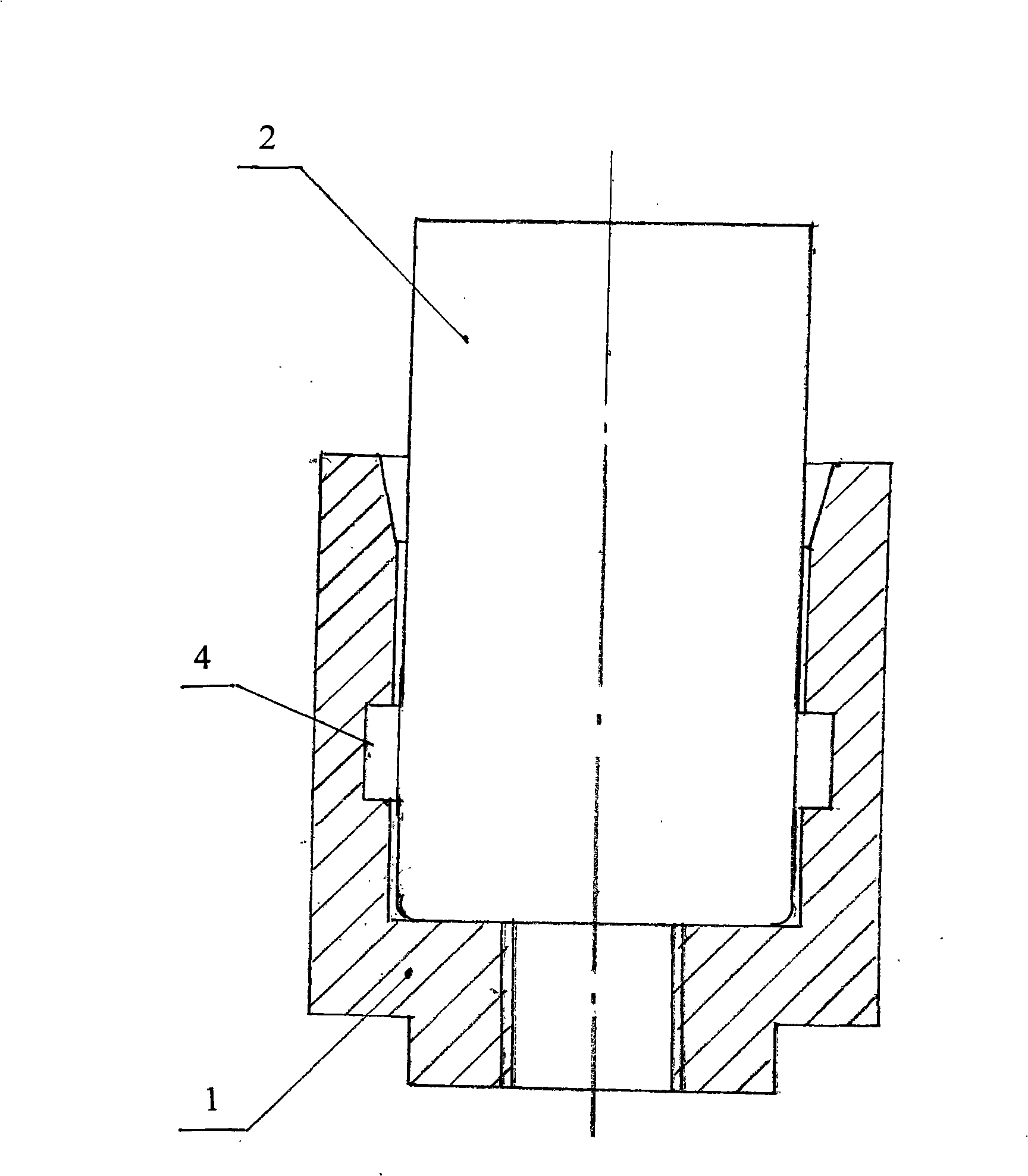
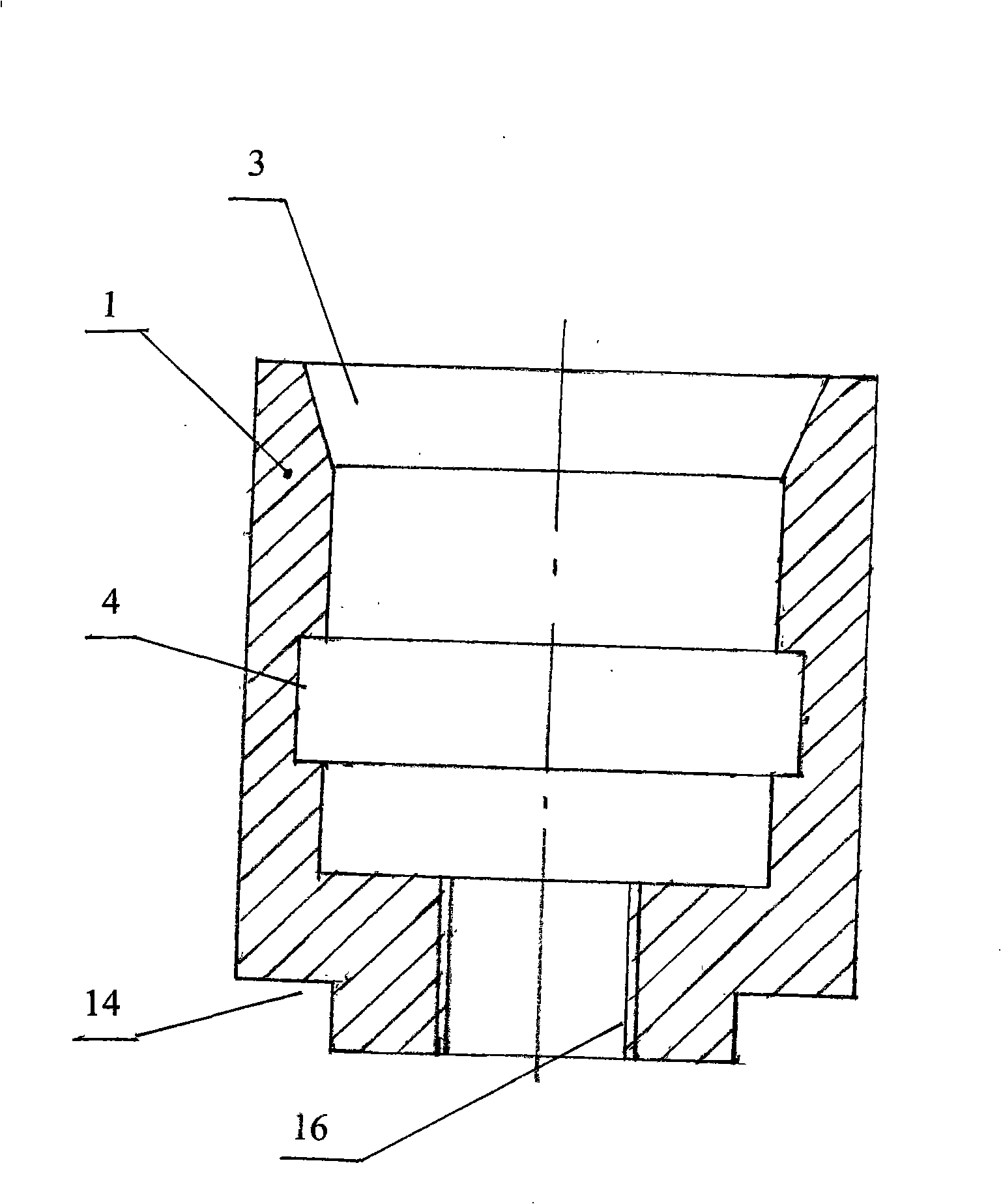
[0027] A female joint 1, the female joint 1 has a central hole 3, and an annular groove 4 is formed on the inner peripheral surface of the central hole 3;

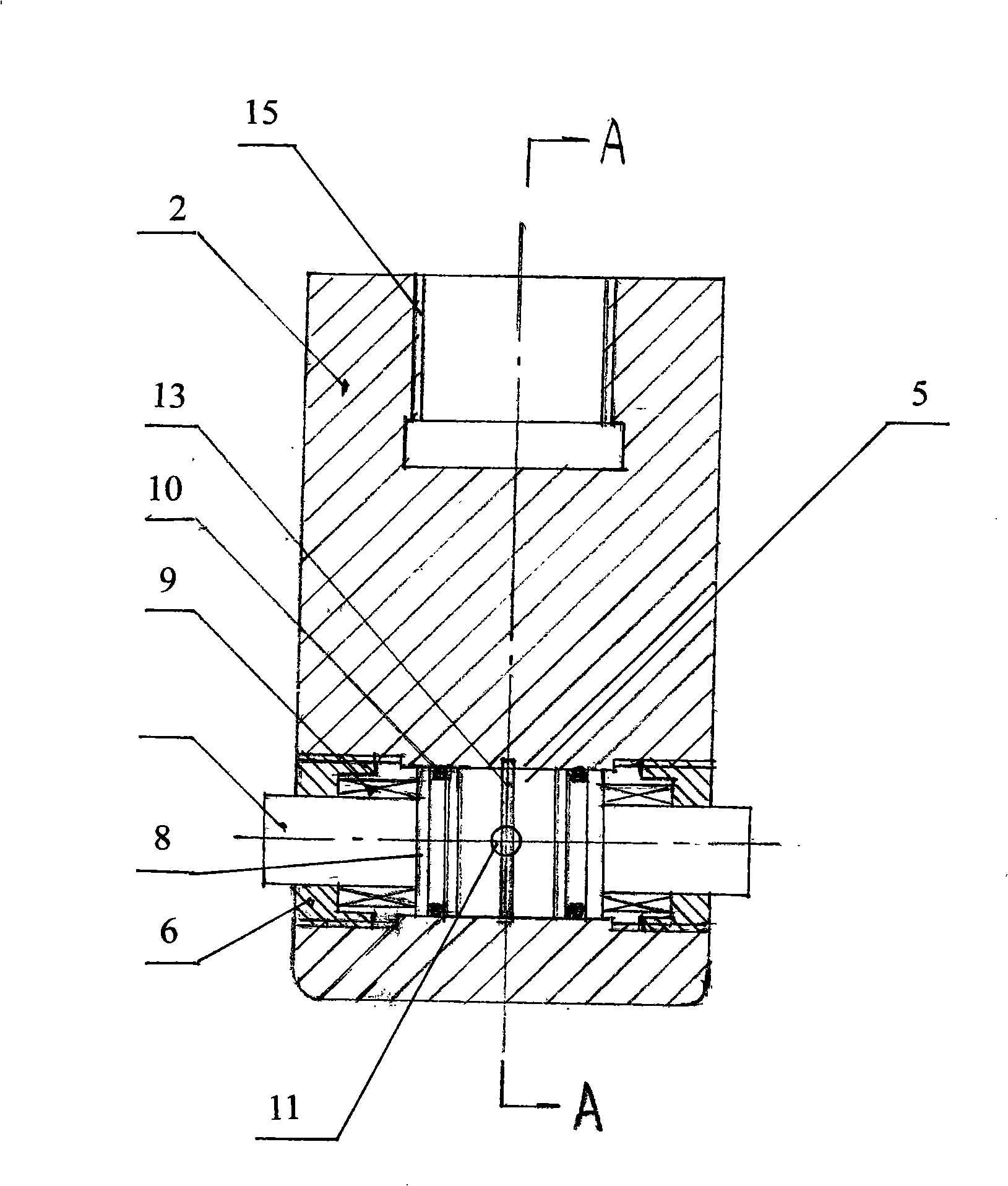
[0028] A male joint 2, a section of the male joint 2 is movable in the central hole 3 of the female joint 1; the lower section of the male joint 2 has a radial perforation 5, and the two ends of the radial perforation 5 have internal threads and are respectively fixedly connected with locking Coils 6, each locking coil 6 is movably socketed with a movable small shaft 7 with an annular boss 8 at the inner end, and a spring 9 and a sealing ring 10 are sleeved on the movable small shaft 7 in the radial perforation 5; There is an oil inlet and outlet hole 11 in the male joint 2 that one end communicates with the radial perforation 5 and the other end passes through.

[0029] A retaini...

Embodiment 2

[0032] Embodiment 2: refer to each accompanying drawing.

[0033] A hydraulic expansion joint, the structural composition of which includes:

[0034] A female joint 1, the female joint 1 has a central hole 3, and an annular groove 4 is formed on the inner peripheral surface of the central hole 3;

[0035] A male joint 2, a section of the male joint 2 is movable in the central hole 3 of the female joint 1; the lower section of the male joint 2 has a radial perforation 5, and the two ends of the radial perforation 5 have internal threads and are respectively fixedly connected with locking Coils 6, each locking coil 6 is movably socketed with a movable small shaft 7 with an annular boss 8 at the inner end, and a spring 9 and a sealing ring 10 are sleeved on the movable small shaft 7 in the radial perforation 5; There is an oil inlet and outlet hole 11 in the male joint 2 that communicates with the radial perforation 5 at one end and passes through at the other end;

[0036] A r...


PUM


Abstract

A hydro-bulging movable joint is characterized in that the movable joint comprises a concave joint with a central hole; a ring-shaped concave slot is formed at the inner peripheral surface of the central hole; the movable joint further comprises a convex joint; a section of the convex joint is disposed in the central hole of the concave joint; a radial perforation is formed at the lower section of the convex joint; inner screw threads are formed at the two ends of the radial perforation, and the two ends thereof are connected with locking helicoids; a small movable shaft provided with a ring-shaped lug boss at the inner end thereof is movably sleeved in each locking helicoid; a spring and a sealing ring are sleeved on the small movable shaft in the radial perforation; an oil intake and discharge hole is arranged in the convex joint, wherein one end of the oil intake and discharge hole communicates with the radial perforation, and the other end thereof passes out of the radial perforation. By adopting the movable joint, connection and detachment are rapid and convenient. The movable joint can be widely used for movable connection between hydraulically controlled carriages of automobiles or trains, and between drill stems in geological or oil drilling, and can also be used in equipment for disposing urban refuse.

Description

technical field [0001] The invention belongs to a quick coupling joint made of metal, hydraulically controlled, and kept connected by a locking element, and relates to a hydraulic expansion joint, which is suitable for the flexible connection between parts, and is especially suitable for garbage collection and transfer compression in the device. Background technique [0002] In industrial products and actual production, there are many fields that require movable connections, such as the movable connections of automobiles and train carriages, the movable connections of drill pipes in geological oil drilling, and the hanging, dragging and holding connections between various industrial products Etc.; In the prior art, the movable connection between the carriages of automobiles or trains and the movable connection device of drill rods in geological oil drilling all have more complicated structures, and in use, multiple steps must be operated to complete the connection; For exam...

Claims


Application Information

Patent Timeline
IPC IPC(8): F16B21/00B65F1/14B65F9/00
Inventor 贾林黎春进
Owner 贾林
Why Eureka
Try Eureka