System and method for positioning split joint wall based on image inductor

An image sensor and positioning system technology, which is applied in the input/output process of instruments, data processing, electrical digital data processing, etc., can solve the problem of slow refresh rate and inability to meet the large-size and high-precision positioning requirements of large-screen splicing walls , Infrared long-distance receiving effect is poor, etc.

Inactive Publication Date: 2008-12-17
GUANGDONG VTRON TECH CO LTD
View PDF1 Cites 28 Cited by
  • Summary
  • Abstract
  • Description
  • Claims
  • Application Information

AI Technical Summary

Problems solved by technology

Among them, the infrared touch screen is a device with relatively high performance and wide application in the touch screen positioning technology. However, the infrared touch screen device also has its inherent shortcomings and limitations. The gradual aging of components will affect the receiving effect of the receiving end of the infrared touch screen device. In addition, the infrared long-distance receiving effect is relatively poor, which limits the screen size of the splicing wall based on the infrared touch screen, etc.
In addition, the patent application with the application number 200610122739.5 discloses a positioning device and positioning method based on a CMOS digital image sensor. Handwriting positioning, because the size of the large-screen splicing wall is very large, the corresponding amount of data to be processed is also large, using the existing positioning method for processing correspondingly has a large amount of data transmission, takes up a lot of computer resources, and slow refresh speed , poor interactive performance and other defects, unable to meet the large-size and high-precision positioning requirements of the large-screen splicing wall, resulting in positioning deviation

Method used


Image

  • System and method for positioning split joint wall based on image inductor
  • System and method for positioning split joint wall based on image inductor
  • System and method for positioning split joint wall based on image inductor

Examples


Embodiment Construction

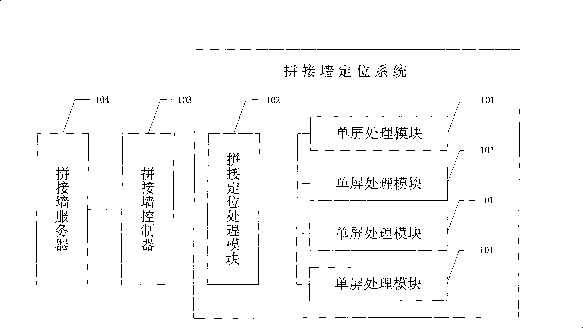
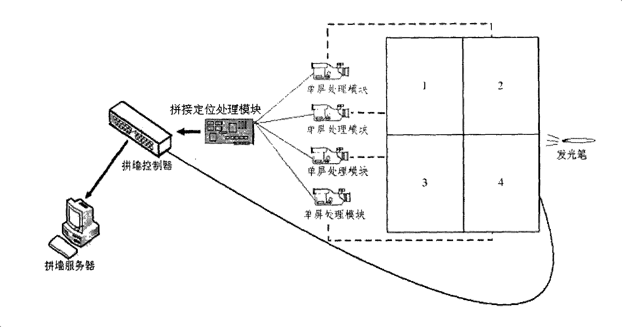
[0027] Such as figure 1 As shown, it is a schematic structural diagram of the video wall positioning system based on the image sensor of the present invention, figure 2 Shown is a schematic diagram of the composition of the positioning system.

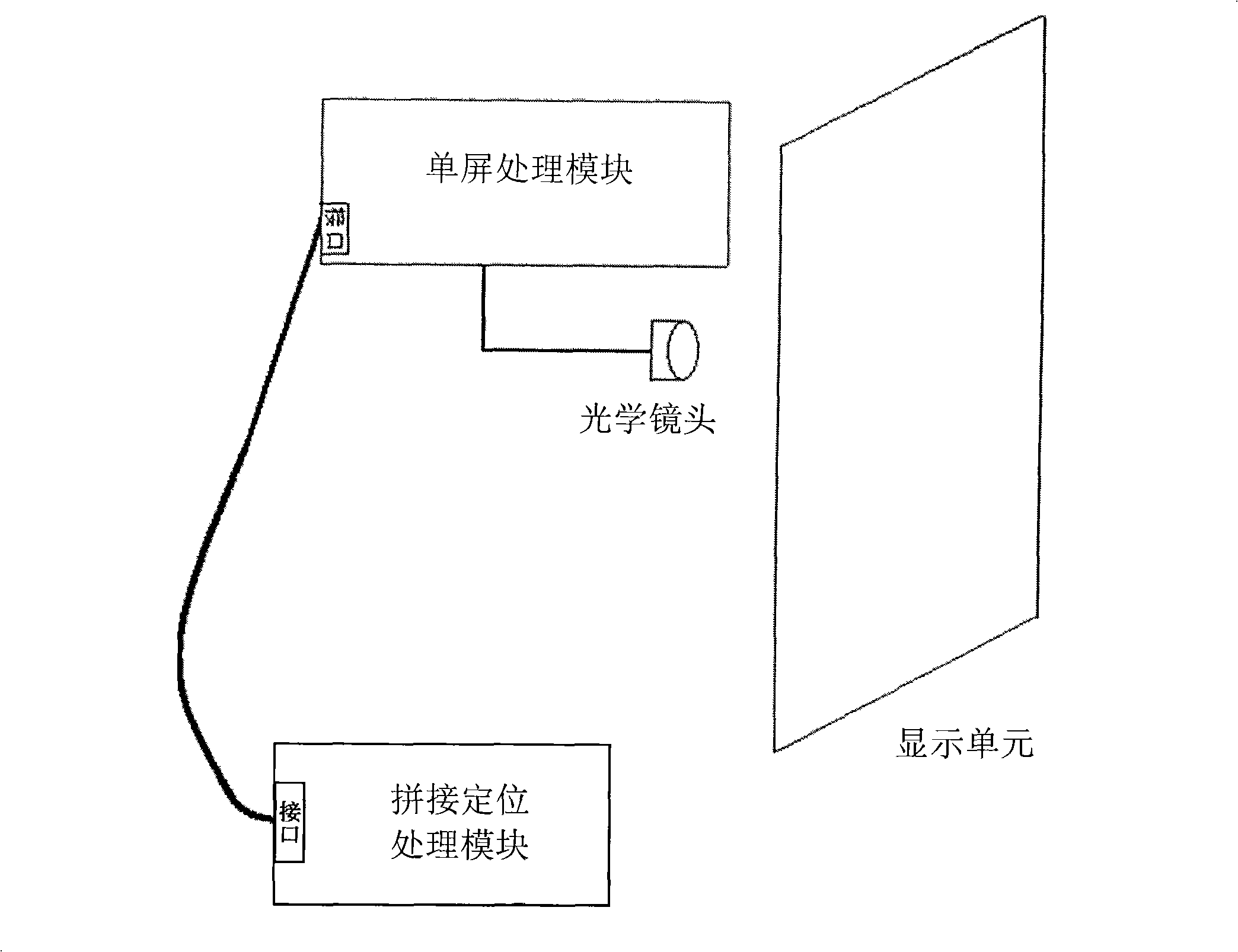
[0028] Such as figure 1 As shown, it is a schematic structural diagram of the video wall positioning system based on the image sensor of the present invention, which includes at least two or more single-screen processing modules 101 and a splicing positioning processing module connected to the single-screen processing modules 101 102, wherein any single-screen processing module 101 corresponds to one of the display units of the splicing wall;

[0029] The single-screen processing module 101 is configured to collect the luminance value of each pixel of the display unit, and perform binarization processing on the luminance value of each pixel according to a preset pixel threshold, and calculate the brightness value of each pixel in th...


PUM


Abstract

The invention relates to a stitching wall positioning system based on an image sensor and a positioning method. The stitching wall positioning system comprises at least two single-screen processing modules and a stitching and positioning processing module connected with the single screen processing modules, wherein any single-screen processing module is corresponding to a display unit of the stitching wall, and the single screen processing modules respectively collect the brightness values of all pixel points of the corresponding display units, perform the corresponding processing and obtain the number of the pixel points of light spots and the first position coordinate of the center points of the light spots relative to the display units; the stitching and positioning processing module calculates the second position coordinate of the center points of the light spots relative to the stitching wall, and realizes the positioning. Because the positioning of the stitching wall is realized based on the image sensor, the positioning performance is not easy to be affected by long-term usage, and because each single-screen processing module performs processing to the brightness value of the corresponding display unit, the processed data size is small, the processing speed is high and the positioning precision is improved.

Description

technical field [0001] The invention relates to the technical field of splicing wall positioning, in particular to an image sensor-based splicing wall positioning system and a positioning method thereof. Background technique [0002] With the continuous integration and development of display technology and control technology, in the high-end engineering field, the application of large-screen splicing wall display systems is becoming more and more extensive. At present, large-screen splicing display technology mainly adopts multiple rear-projection splicing walls, such as CRT rear-projection display walls, LCD rear-projection display walls, DLP rear-projection splicing walls, and plasma display walls. The super large screen, multi-screen display and clear and realistic display effect brought by it have greatly improved the work efficiency in monitoring, security, conference, simulation and other fields, and at the same time promoted the rapid progress of the technical level o...

Claims


Application Information

Patent Timeline
Patent Type & Authority Applications(China)
IPC IPC(8): G06F3/042
Inventor 张军杨月
Owner GUANGDONG VTRON TECH CO LTD
Why Eureka
Try Eureka