
Recovery of inert gas from a fuel cell exhaust stream

An inert gas and fuel cell technology, applied in fuel cells, fuel cell groups, fuel cell additives, etc., can solve problems such as hindering, preventing the flow of gaseous reactants, and affecting fuel cell performance

Inactive Publication Date: 2008-12-17
GM GLOBAL TECH OPERATIONS LLC
View PDF4 Cites 11 Cited by
  • Summary
  • Abstract
  • Description
  • Claims
  • Application Information

AI Technical Summary

Problems solved by technology

Water retention can impede or prevent the flow of gaseous reactants and severely impact fuel cell performance

Method used


Image

  • Recovery of inert gas from a fuel cell exhaust stream
  • Recovery of inert gas from a fuel cell exhaust stream
  • Recovery of inert gas from a fuel cell exhaust stream

Examples


Embodiment Construction

[0024] The following description is merely exemplary in nature and is not intended to limit the disclosure, application or uses. It should also be understood that throughout the drawings, corresponding reference numerals indicate like or corresponding parts and features. With respect to the disclosed methods, the steps given are exemplary in nature and thus not essential or critical.

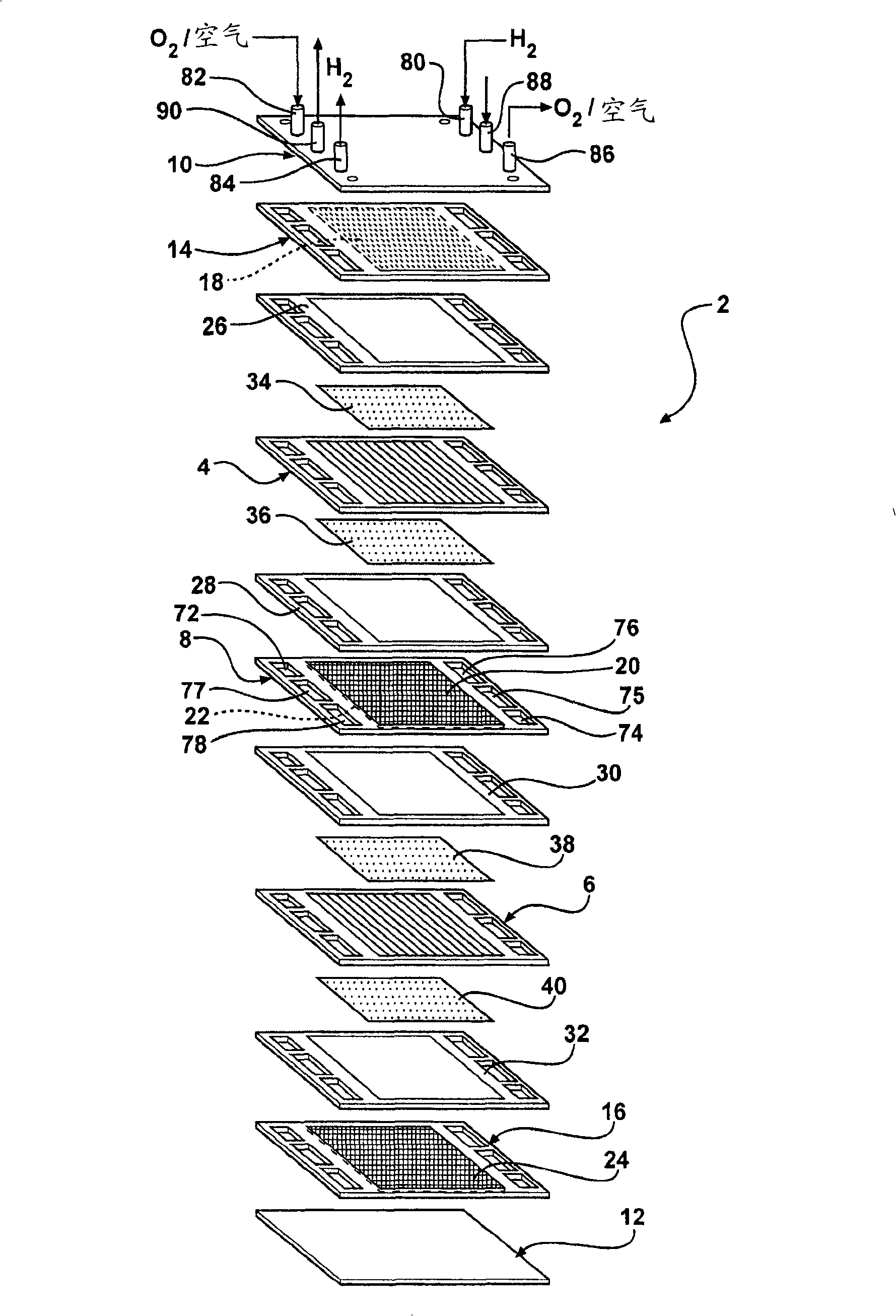
[0025] For simplicity, only a 2-cell stack (ie, one bipolar plate) is illustrated and described below, it being understood that a typical stack will contain many more such cells and bipolar plates. Also for the sake of simplicity, only one fuel cell stack (ie a certain number of fuel cells connected in series) is illustrated and described below. Those of ordinary skill in the art will also appreciate that more than one fuel cell stack, such as a dual-stack system, may be used within the scope of the present invention.

[0026] figure 1 A 2-cell bipolar PEM fuel cell stack 2 having a pair of M...


PUM


Abstract

A fuel cell system is provided including a fuel cell stack having a fuel cell having an anode, an anode outlet, an anode inlet, and a cathode. The fuel cell system further includes a hydrogen pump in communication with the anode outlet and the anode inlet. The hydrogen pump features a proton exchange membrane disposed between a first electrode and a second electrode. The first electrode is configured to accept an anode outlet stream from the anode outlet, the anode outlet stream including a hydrogen gas and an inert gas, the first electrode being configured to exhaust the inert gas. In one embodiment, the hydrogen pump is in communication with a PROX unit and configured to provide the hydrogen gas to the fuel cell stack. Further provided are methods employing the hydrogen pump wherein a start-stop degradation of the fuel cell is militated against and a hydrogen feed stream is humidified.

Description

technical field [0001] The present invention relates to fuel cell systems, and more particularly, to methods of mitigating start-stop degradation and humidifying hydrogen fuel within fuel cell assemblies. Background technique [0002] Fuel cells have been proposed as clean, efficient and environmentally friendly power sources for electric vehicles and a variety of other applications. One example of a fuel cell is a proton exchange membrane (PEM) fuel cell. A PEM fuel cell consists of a membrane-electrode-assembly (MEA), typically comprising a thin solid polymer membrane-electrolyte, with a catalyst-bearing electrode, eg, an anode or a cathode, on either side of the membrane electrolyte. [0003] MEAs generally comprise porous conductive materials, also known as gas diffusion media, which also form the anode and cathode layers. Fuel, such as hydrogen, is introduced at the anode, where it reacts electrochemically in the presence of a catalyst, producing electrons and protons...

Claims


Application Information

Patent Timeline
Patent Type & Authority Applications(China)
IPC IPC(8): H01M8/04H01M8/06H01M8/02H01M8/24
CPCH01M8/04097H01M8/04231H01M8/0681H01M2008/1095H01M8/04225H01M8/04228H01M8/04302H01M8/04303H01M8/2483Y02E60/50
Inventor B·拉克什马南M·M·费M·维尔H·A·加斯泰格G·R·伍迪D·A·马斯藤
Owner GM GLOBAL TECH OPERATIONS LLC
Learn More