
Method for estimating signal wave direction

A technology for direction estimation and direction of arrival, which is applied in radio/inductive link selection arrangements, diversity/multi-antenna systems, selection devices, etc., can solve the problems of inability to effectively estimate signal direction of arrival, increase in cost, etc., and achieve improved performance , the effect of eliminating the influence of noise

Inactive Publication Date: 2008-12-17
PLA UNIV OF SCI & TECH
View PDF0 Cites 31 Cited by
  • Summary
  • Abstract
  • Description
  • Claims
  • Application Information

AI Technical Summary

Problems solved by technology

When the signal in space arrives at the antenna with different time delays due to multiple paths, there is a correlation between the signals, which makes the above method unable to effectively estimate the direction of arrival of the signal.
The traditional spatial covariance difference method can only estimate the direction of arrival of the signal at the beginning, and can estimate the development of the coherent signal. There are two important shortcomings. One is that the number of antenna elements M must be greater than twice the number of incident signals q , that is, M>2q, and the second is that spectral peaks are formed at ±θ, where θ is the true angle of arrival of the signal
Due to the above two shortcomings, the cost of traditional methods increases in practical applications

Method used

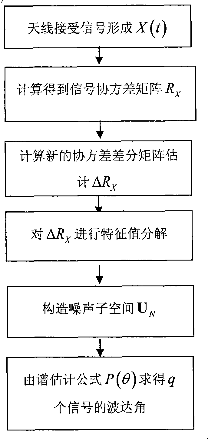

Image

  • Method for estimating signal wave direction
  • Method for estimating signal wave direction
  • Method for estimating signal wave direction

Examples


Embodiment Construction

[0018] For the unknown color noise background, we assume that the noise covariance matrix has a symmetric Toeplitz matrix property. The antenna array is a uniform linear array, each array element is an omnidirectional antenna, the number of array elements is M, and the interval between array elements is d. Assume that q narrowband far-field incoherent signals are distributed from the direction θ i , i=1, L, q, incident to the antenna array.

[0019] Then the data vector received by the array at time t can be expressed as:

[0020] X(t)=AS(t)+n(t)

[0021] where X(t)=[x 1 (t), L, x M (t)] T is the received data vector, A=[a(θ 1 ), L, a(θ q )] is M×q dimension direction matrix, a(θ)=[1, e -j2πd(sinθ) / λ , L, e -j2πd(M-1)(sinθ) / λ ] T is the steering vector corresponding to the incident angle θ, λ is the signal wavelength, S(t)=[s 1 (t), L, S q (t)] T is a q×1-dimensional signal vector, n(t)=[n 1 (t), L n M (t)] T is M×1-dimensional noise vector, () T Represents a ...


PUM


Abstract

The invention provides a signal DOA estimation method. The method supposes that an unknown noise covariance matrix has a symmetrical Toeplitz matrix character; according to the difference conception of the traditional covariance matrix, an imaginary number j is introduced so that the newly constructed covariance matrix changes into a central Hermitian matrix, thereby, the character decomposition can obtain the same DOA as the incident signal numbers. The method greatly reduces the number of the antenna array element required by estimating the signal wave arrival direction, and a wave crest is only formed in the wave arrival direction of the real signal. The method can reduce cost greatly in the practical application.

Description

technical field [0001] The invention relates to a network positioning technology, which uses a smart antenna to estimate the direction of arrival of a signal received by the antenna based on the cognitive radio technology, so as to provide security services, business services, network management and location-related information Services provide technical basis. Background technique [0002] In recent years, with the continuous development of mobile communication technology, positioning technology in mobile communication network has been widely used. Positioning technology can be applied to security services, business services, network management and location-related information services. For example, positioning services can be used for personnel rescue in earthquakes, battlefields, etc., and can also be used for urban traffic navigation, target tracking, and other fields. [0003] According to the positioning accuracy requirements of different location services, the imple...

Claims


Application Information

Patent Timeline
Patent Type & Authority Applications(China)
IPC IPC(8): H04Q7/38H04B7/02
Inventor 郭艳李宁刘学亮王金龙
Owner PLA UNIV OF SCI & TECH
Learn More