Wheel bearing with sensor

A sensor and sensor unit technology, applied in the field of wheel bearings, can solve the problems of high cost and poor productivity.

Inactive Publication Date: 2008-12-17
NTN CORP
View PDF1 Cites 9 Cited by
  • Summary
  • Abstract
  • Description
  • Claims
  • Application Information

AI Technical Summary

Problems solved by technology

Therefore, as in Patent Document 1, when the deformation measuring instrument is attached t

Method used


Image

  • Wheel bearing with sensor
  • Wheel bearing with sensor
  • Wheel bearing with sensor

Examples


Embodiment Construction

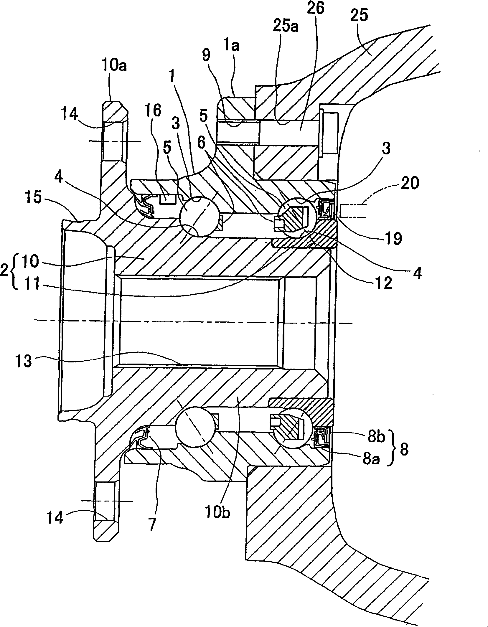
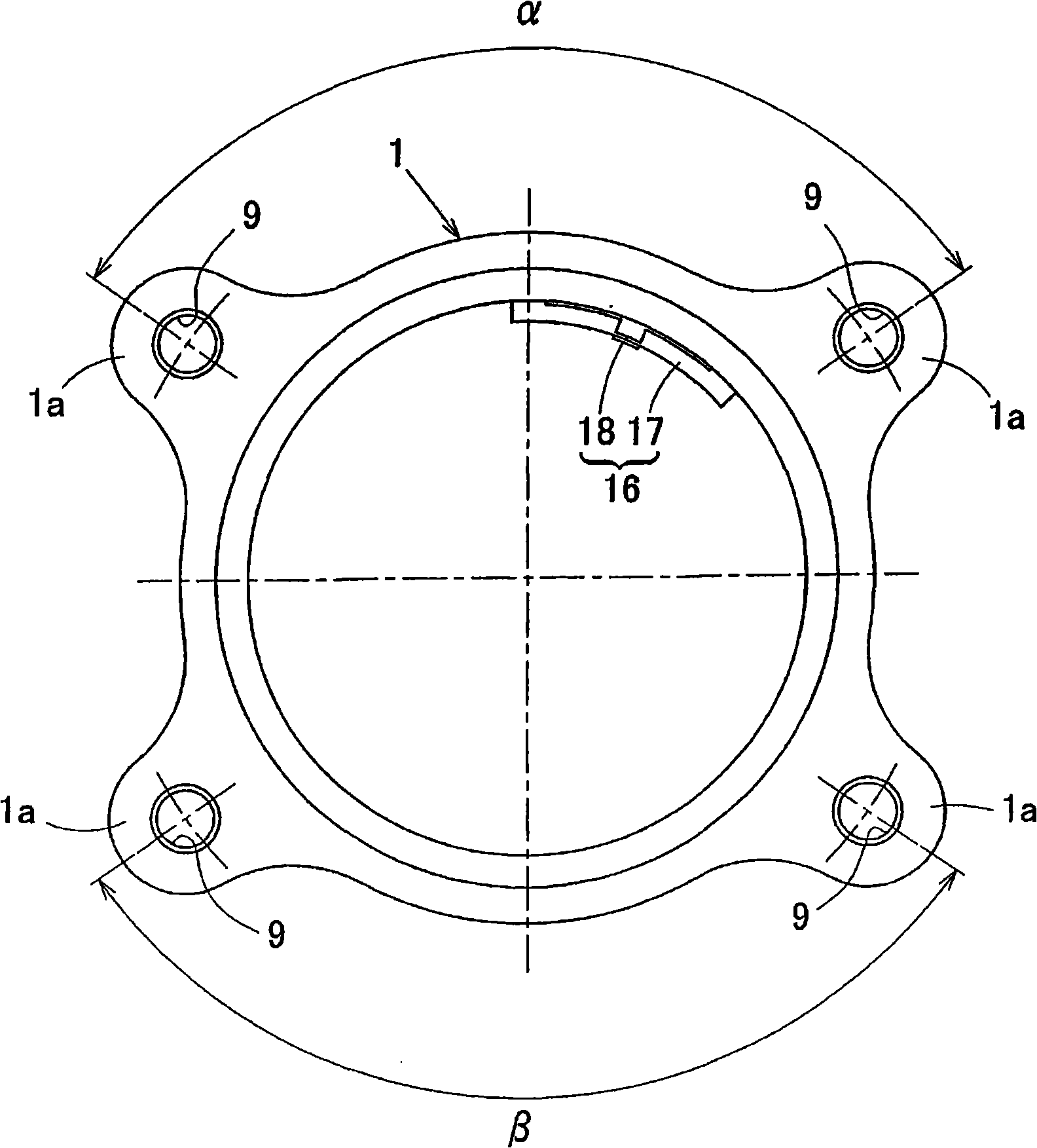
[0062] according to figure 1 ~ Fig. 3 illustrates the first embodiment of the present invention. This embodiment is a third-generation inner ring rotation type, and is suitable for a wheel bearing for supporting a driving wheel. In this specification, when mounted on a vehicle, the side toward the outside in the vehicle width direction of the vehicle is referred to as the outer side, and the side toward the center of the vehicle is referred to as the inner side.

[0063] The wheel bearing comprises: an outer member 1 formed with a plurality of rows of rolling surfaces 3 on the inner periphery; an inner member 2 formed with rolling surfaces 4 facing each of the rolling surfaces 3; sandwiched between these outer members 1 and Multiple rows of rolling elements 5 between the rolling surfaces 3, 4 of the inner part 2. This wheel bearing is a multi-row angular contact ball bearing type, the rolling elements 5 are made of balls, and each row is held by a cage. The rolling surfaces...


PUM


Abstract

A sensor-equipped bearing for a wheel, with which a load detection sensor can be compactly installed on a vehicle, that can detect a load on the wheel, and that can be mass-produced at low costs. The bearing has an outer member having double-row rolling surfaces on its inner surface, an inner member having formed on it rolling surfaces opposite the rolling surfaces of the outer member, and double-row rolling bodies interposed between the rolling surfaces of the inner and outer members. The bearing rotatably supports the wheel relative to a vehicle body. In the bearing, a sensor unit is attached to a stationary-side member out of the outer member and the inner member. The sensor unit is composed of a sensor installation plate and of a strain sensor or a displacement sensor that is attached to the sensor installation member, or alternatively, the sensor unit is composed of an installation member formed from a strain-inducing material and a detection coil that is attached to the installation member. The sensor installation member or the installation member formed from the strain-inducing material has at least two contact/fixation sections engaged to the stationary-side member. The strain sensor or the displacement sensor or the detection coil is placed at at least one portion between adjacent contact/fixation sections.

Description

technical field [0001] The present invention relates to a sensor-equipped wheel bearing incorporating a load sensor for detecting a load applied to a bearing portion of a wheel. Background technique [0002] Conventionally, for safe running of automobiles, sensors for detecting the rotational speed of each wheel are provided on wheel bearings. Conventional measures to ensure the running safety of ordinary automobiles are carried out by detecting the rotation speed of the wheels of each part. However, detection of the rotation speed of the wheels alone is not sufficient, and a technology that can further perform safety control using other sensor signals is sought. [0003] Therefore, there is also considered a technique of realizing attitude control based on the load acting on each wheel when the vehicle is running. For example, when turning, a large load is applied to the outer wheel. In addition, when driving on a left-right inclined surface, the load is concentrated on on...

Claims


Application Information

Patent Timeline
IPC IPC(8): G01L5/00B60B35/18F16C19/18F16C19/52F16C41/00G01D5/245
Inventor 尾崎孝美石河智海西川健太郎
Owner NTN CORP
Why Eureka
Try Eureka